This article will explain the fire extension potential and probabilities in lightweight wood-frame buildings by providing an understanding of the numerous combustible void spaces created by the construction methods and materials in large wood-frame buildings.
- Toothpick Towers: A Fire Officer’s Guide to Operating in Lightweight Wood-Frame Multiple Dwellings
- Lightweight Wood-Frame Construction Concerns in Fast-Food Restaurants
- Modern Wood-Frame Construction: Firefighting Problems and Tactics
First, we define “lightweight wood-frame” as buildings that are constructed with some form of lightweight engineered wood structural element or elements—i.e., wood I-joists, which are commonly used in floor systems and as rafters. Parallel-chord wood trusses may be used in floor or flat-roof systems. Sloped and peaked wood trusses are used in the roofs of buildings and are manufactured in many configurations and pitches to meet the architectural needs of the designer. Dual- or mono-pitch, scissor truss, and sloping flat trusses are examples of the truss designs and associated shapes that are presented by the finished product.
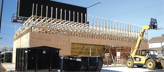
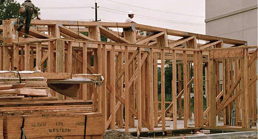
(1) The A side of the building. Convenience store occupancies will have fewer areas of windows than fast-food restaurants. (Photos by author.)
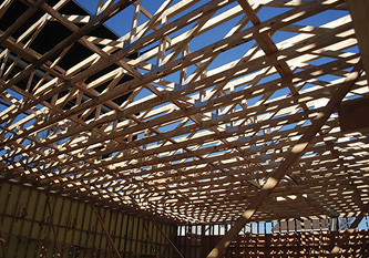
(2) The view of the sloped roof trusses, which span from the A to C sides of the building. The trusses allow for an open-floor plan without interior columns or bearing walls. The truss loft will be filled with building utilities such as wiring, plumbing, HVAC, and beverage-dispensing systems.
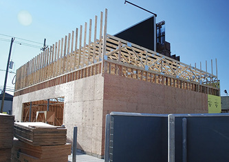
(3) The A/D corner of the building. Depicted is the part of the truss that extends above the roofline, which will create the parapet. The parapet will conceal the roof-mounted utilities, including HVAC equipment.
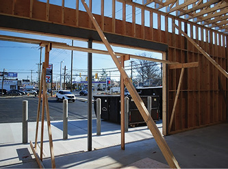
(4) A structural steel column and beam assembly is used to create the large opening in the A-side wall, which will accommodate the entry door and storefront windows.
The Buildings and Construction Features
The size of lightweight wood-frame buildings will vary from a single-story fast-food restaurant approximately 3,000 to 5,000 square feet in floor area to five- and six-story multiple dwellings with floor areas of 40,000 or greater square feet per floor. The McDonald’s fire in Houston, Texas, on February 14, 2000, which resulted in the line-of-duty death of two Houston Fire Department members, was 110 × 39 feet, or 4,290 square feet in floor area. This fire should be studied by every member of the fire service who may respond to a fire in a fast-food restaurant or similar occupancy. (The National Institute for Occupational Safety and Health’s report on this fire can be found at bit.ly/3Rm6t9t.) Other occupancy types constructed in a manner similar to fast-food restaurants include convenience stores and bank branches (photos 1-4).
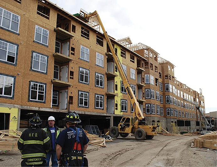
The most obvious—and one of the largest—combustible voids in lightweight wood-frame buildings are created by sloped, peaked, or parallel-chord roof trusses. The size and volume of the combustible void space created by these structural components will vary based on several factors, including the building’s square footage, the slope or rise and run1 of the roof trusses, and the dimension between the top and bottom chords of parallel-chord trusses.
Some peaked and sloping roof trusses have only a slight pitch (photo 5), while others have a significant pitch (photo 6). The more significant the pitch, the greater the volume of the combustible void space. Larger-square-foot buildings often have a steeper pitch to the roof trusses; this factor will have an impact on the reach of the hose stream into the truss loft.
In addition, there may be numerous obstructions to hose stream penetration into the void space such as insulation at the ceiling level, above the drywall or other ceiling material, the web members of the trusses, catwalks, or other areas where flooring is installed to allow access for contractors; for heating, ventilation, and air-conditioning (HVAC) ducts; and to create air and exhaust ducts for the cookline ventilation system in food establishments (photo 7).
The other obvious—and perhaps greatest—concern to firefighters is the combustible void space created by the use of parallel-chord floor trusses. This area or size of the combustible void space created by the floor trusses will vary based on a number of factors, including the square footage of the building, the square footage of individual dwelling units, and the spacing of code-required fire blocking and fire separation walls.
The construction of single-story buildings with lightweight wood truss roofs has increased significantly over the past 25 to 35 years. The buildings and occupancy types include fast-food or other types of restaurants, office occupancies, small mercantile occupancies, bank branches, and daycare centers (photo 8), to name a few. Examining these buildings during the early phase of construction may be misleading, as some of these buildings may be constructed partly with exterior walls of concrete block, steel columns, and steel stud infill walls, leading us to believe the construction type may not be wood frame.
(5) A fast-food restaurant with a lightweight wood truss roof with a minor slope. The trusses span from the B-side wall to the D-side wall. Trusses with a slight pitch will result in a small combustible void space as compared to peaked-roof trusses with a greater pitch.
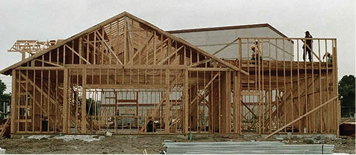
(6) A restaurant under construction. The trusses have greater pitch than the trusses in photo 5, resulting in a larger combustible void space. The entire volume of the void space will have to be filled with heat before the effects of the heat may be felt at floor level. The void space has the potential to conceal a significant volume of fire.
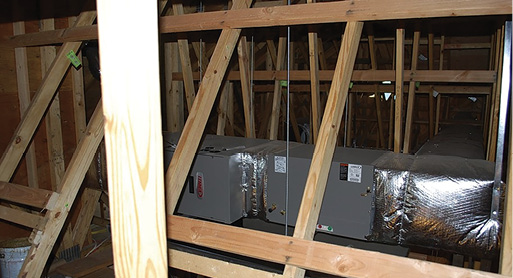
(7) An HVAC unit and the floor or catwalk installed in a truss void.
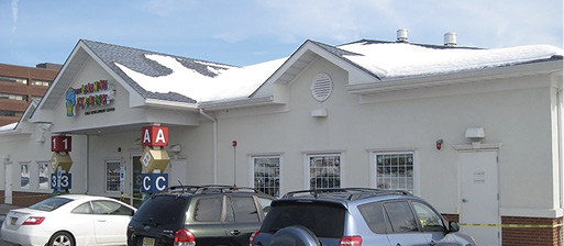
(8) This daycare center is an example of a single-story wood-frame building with lightweight wood peaked-roof trusses.
Another feature of the single-story commercial occupancy is the vertical dimension between the floor and the ceiling, which results in a higher ceiling than the typical residential occupancy. In some occupancies, the trusses are left exposed and become part of the interior finish of the occupancy. This construction feature will allow you to easily recognize any fire up in the truss area, and hose streams should have easy access to the fire in the trusses. The downside to the exposed trusses is that they will quickly be exposed from a contents fire below them.
Firefighters must recognize and be able to identify a fire in the truss roof assembly early on in an incident. The size of the combustible void space, especially when the area of the building is larger and the roof has greater pitch, creates a significant volume of space that needs to be filled with heat and other products of combustion before responding companies may feel the effects of the heat on the floor below. The heat condition may also be masked by the drywall and insulation material installed at the ceiling level.
Often, we determine how significant the fire may be by how much heat is banked down, causing firefighters to crawl. Although the tactic may be useful in dwelling fires with eight- or nine-foot-high ceilings, this tactic will be very misleading in commercial buildings that have nine-foot-plus ceiling heights and large combustible voids created by the use of peaked, sloping, or parallel-chord roof trusses.
Recognizing the potential for fire in the void is key. The odor of wood burning when you step off the rig or a slight haze across the ceiling should cause the firefighters to understand the conditions above their heads by opening the ceiling immediately on entering a structure.
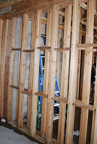
(9) A dwelling unit separation wall, which is constructed with double 2- × 4-inch studs, which are staggered and braced with horizontal blocking at two locations in each stud bay. The horizontal blocking may be required by the design of the rated wall assembly. At this stage of construction, it is unlikely the finished wall will contain core board; rather, the stud bays will be filled with mineral wool insulation batts and finished with one or more layers of fire-rated gypsum board on each side of the wood studs facing the interior of each dwelling unit.
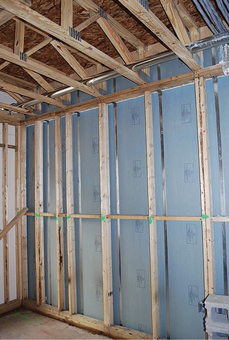
(10) The construction of a double-stud fire separation wall with core board or shaft liner gypsum board. The core board or shaft liner is attached with metal straps or clips to each side of the wood studs. This construction method will ensure the integrity of the fire separation wall in the event of a collapse of the building on one side of the fire separation wall.
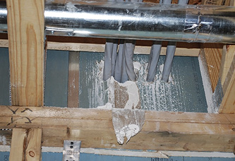
(11) Electric utility cables run through the floor truss loft and penetrate the fire separation wall that separates dwelling units. Poor construction techniques and the lack of compliant fire-stopping will negate the ability of the fire separation wall to prevent the passage of fire through it.
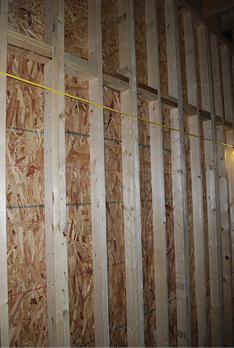
(12) An interior shear wall constructed with 2- × 4-inch studs 12 inches on center with oriented strand board. Construction of shear walls in this manner eliminates the ability of firefighters to breach the wall and perform a reduced profile maneuver to move from one room to another.
Fire Separation Wall and Ceiling Assemblies
Building codes require fire separation walls and fire blocking at various construction assemblies in multifamily residential buildings. Most commonly, fire separations are required at the walls that separate the dwelling unit from the corridor and the walls that separate one dwelling unit from another. Fire blocking will be required between the I-joist or trusses along these wall lines between the ceiling and the underside of the floor deck. The ceilings of dwelling units and corridors are also typically fire-rated assemblies.
A fire separation wall is a distinct construction feature that should not be confused with a fire wall. By definition, a fire wall has a footing and foundation and will run vertically, from the foundation up through the height of the building, and terminate at the underside of the roof decking or extend through the roof of the building, terminating above the roofline. Fire walls are typically constructed with a masonry element such as concrete block. In theory, the structures on both sides of a fire wall may collapse, and the fire wall will remain standing. Conversely, a fire separation wall, also referred to in construction industry terms as a “sep” wall or “fire partition,” is constructed as an assembly in accordance with a “listing” that determines the hourly rating and construction methods and materials used in the construction of the “listed” fire-rated assembly. Fire separation walls or fire partitions are required to be constructed in accordance with the assembly’s “listing” (photos 9-11).
Fire-rated ceiling assemblies are constructed in the same manner. A fire separation wall or fire partition is commonly constructed of double 2- × 4-inch or 2- × 6-inch wood studs with layers of fire-rated gypsum board, core board (which is gypsum board), and layers of fire-rated gypsum board with the stud bays being filled with fire-safing insulation (a mineral wool insulation material).
Other listed wall assemblies may be constructed with a single 2- × 4-inch or 2- × 6-inch stud wall with fire-safing insulation in the stud bays and one or more layers of fire-rated gypsum board on each side of the wood-frame wall. In taller, larger wood-frame multiple dwelling walls, the lower floors may be constructed with 2- × 6-inch studs, with sheathing installed over the studs to support the load or weight of the structure or the stories above and to perform as shear walls2 (photo 12).
Construction features and methods may not ensure that the fire separation walls are constructed in accordance with their listing and, in instances where utility installations penetrate the fire separation walls, the listed assembly may not be properly fire-stopped or installed in accordance with the assembly’s listing.
(13) The construction of the first level of a podium or pedestal building of cast-in-place reinforced concrete columns, bearing walls, and floor slab. This construction is common if the first level is used as a parking level. Parking levels usually have a lower celling height than buildings that are constructed with a steel skeleton frame, which may house some form of commercial occupancy on the first floor.
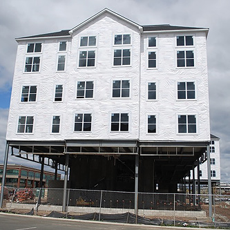
(14) The construction of the building’s podium or pedestal with steel columns and beams and a steel pan deck with a poured concrete floor. This construction method is often used in buildings where the first floor will be occupied as commercial space. The larger vertical dimension of the first level allows for the installation of utilities that will service the first floor, which will be concealed with a suspended ceiling. The exterior walls in this method of construction will be nonload-bearing walls.
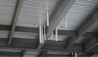
(15) The numerous penetrations of the concrete floor for the drain, waste, and vent plumbing utility, which connects to the building sanitary sewer. A steel column and beam assembly supports the poured concrete floor over the steel decking.
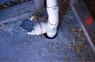
(16) A PVC drain, waste, and vent plumbing pipe penetrates the concrete floor slab. The lack of proper or improperly installed fire-stopping materials will allow vertical fire extension through the annular space between the PVC and the concrete floor slab to the combustible void spaces in the wood framing above the concrete floor slab.
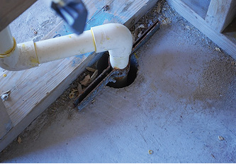
(17) Nonexistent fire-stopping materials or improperly installed fire-stopping materials the fire barrier created by the concrete floor slab. The drain, waste, and vent plumbing utility runs vertically through the building, into the attic or cockloft space, and through the roof.
Multistory Residential Buildings
Three- to six-story wood-frame multiple dwellings may contain many units and have a floor area of as much as 40,000 square feet per floor. The first and, sometimes, second level of pedestal or podium buildings are typically constructed by one of two methods: (1) The walls, columns, and floors are cast-in-place reinforced concrete (photo 13) or (2) structural steel creates a steel skeleton frame for the first floor with a steel pan with poured concrete floor deck (photo 14). In both methods, the floor deck creates the code-required fire separation between the parking and commercial space on the lower floors from the residential occupancy on the floors above. The concrete floor is a formidable fire barrier and serves as the load transfer slab for the wood-frame bearing walls imposed or bearing on the concrete slab.
There will also be various utility penetrations of the concrete slab such as electric utilities; drain, waste, and vent plumbing utility; natural gas services; and refuse shafts. Fire originating on the level below the concrete floor slab may extend into the vertical combustible voids, which run vertically through the building. Of significant concern to the fire service is the potential for nonexistent or improperly installed fire-stopping materials or systems in the concrete floor slab (photos 15-17). Additionally, the exit stairways and elevator shafts will penetrate the concrete floor slab.
Of all the penetrations of the concrete floor slab, the exit stairway and elevator shafts will be the most robust of penetrations, as the exit stairway and elevator shafts will be constructed of cast-in-place reinforced concrete or concrete block. In most wood-frame buildings, the floors may have a slight gap between the exit stair and elevator shafts and the wood framing; if not properly fire-stopped, this will allow for fire extension between the shaft wall and the wood framing (photo 18). The only code-permitted utility penetrations through the stairway walls are those of the utilities serving the stairway such as the electric utility that serves the stairway and fire protection system piping.
Vertical shafts, utility chases, and refuse/recycling chutes are of significant concerns to firefighters. Water supply; drain, waste, and vent; and electric utilities are often run vertically through the building in shafts or chases. Natural gas and electric utility and refuse/recycling chutes will likely extend from the lowest level of the building, often penetrating the first floor’s concrete floor slab, continuing to the uppermost floor of the building. Drainage, waste, and vent lines and refuse/recycling chutes will extend through the attic or cockloft and penetrate through the roof. Fire originating in or extending into a shaft or utility chase will travel the vertical length of the shaft.
Photos 18 and 19 show the ground-floor level, where the trash chute and electric utility feed individual dwelling unit electric service panels. The electric cables will transition horizontally, penetrating the shaft wall at each floor. Each horizontal penetration of the shaft wall creates a potential path for fire extension if the penetrations are not properly fire-stopped.
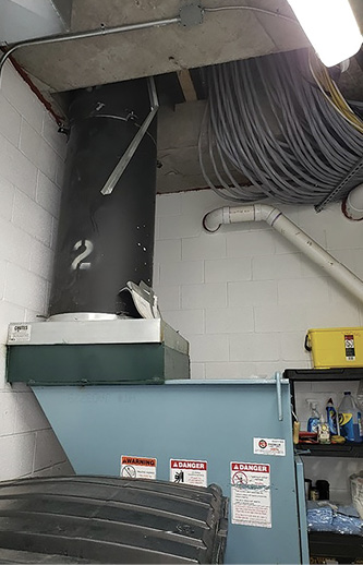
(18) The room on the lowest level of a pedestal-type building, where the trash chute terminates and the electric utility runs vertically in a shaft. This shaft represents a significant potential for fire extension.
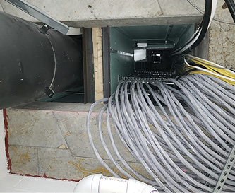
(19) The vertical shaft of the trash chute and the electric service cable runs vertically through the shaft and transitions horizontally, penetrating the shaft wall to each dwelling unit.
Utility Chases and Shafts
The terms “utility chase” and “shaft” are not interchangeable; each has unique construction characteristics that firefighters must understand. A utility chase in a wood-frame building is an enclosed space used to vertically run and conceal piping and other building utilities. The size of the chase will depend on the number and size of the utilities being concealed by the chase. Utility chases are required to be properly fire-stopped at each floor/ceiling assembly or floor level. Larger utility chases will result in larger-volume void spaces. Absence of the code-required fire-stopping (or improperly installed fire-stopping) will allow for vertical fire extension in utility chases.
A utility shaft is a construction feature that runs vertically through a building, providing for utility runs without installing fire-stopping at each floor/ceiling level. In large wood-frame multiple dwellings, the shaft terminates at grade or below grade level in the building’s utility space. The walls of a utility shaft are required to be constructed in accordance with “listed’ fire rating assemblies. The fire rating of the shaft walls eliminates the need for fire-stopping at each floor/ceiling level.
Both utility chases and shafts will likely be vertically stacked in a building, allowing the utility runs and other building elements in a utility chase or shaft to access all floors in a building or to serve all the dwelling units in a vertical line.
Identifying Utility Chases and Shafts
Vertical utility chases and shaft voids can often be discovered by opening walls and ceilings around bathrooms and kitchens, as these areas will have a concentration of vertical chases or shafts containing the various aforementioned utilities.
Other areas where there will be a concentration of utilities will be electric and telecommunication closets and HVAC equipment closets, which are typically stacked vertically on each floor of the building. These utility rooms or closets will be accessible from the common corridor or may be in the core area or near the elevator lobby on the floors of a building. These utility closets or rooms are stacked vertically through the building, providing utilities services to each floor of the building.
Preplanning
One firefighting problem and consideration that results from large floor plans is long, narrow corridors, which require very long hose stretches. Some buildings have incorporated “smoke doors” or “control doors” to separate the corridors into two separate spaces, placing standpipe outlets on each side of the smoke or control doors.
Although some fire departments have embraced the use of these standpipe outlets, which will reduce the hose stretch, there are certain risks associated with this tactic, including, but not limited to, the following:
- The hoseline will not be stretched from the safe haven of the exit stairway.
- Connecting in the corridor will immediately expose the hoseline to the products of combustions when the control or smoke doors are opened.
- A firefighter using the hoseline to get back to the stairway will find himself at the standpipe outlet in a smoke-contaminated corridor.
The importance of conducting formal preplans and building familiarization tours cannot be overstated. Also, conduct site visits and perform photographic documentation of construction methods and materials. Incorporate the information gathered during the construction phase into department training programs.
Understanding the construction methods as well as the materials of a lightweight wood-frame building is paramount for the fire service. Also, understanding the various void spaces created by these construction methods and materials will be invaluable when fighting a fire in one of these buildings.
The fire service has not and will not stop fighting fires in lightweight wood-frame buildings. Understanding the construction methods and materials and understanding the fire spread and collapse potential associated with these buildings will allow the fire service to choose an aggressive strategy and employ sound tactics to provide a positive outcome for occupant evacuation, firefighter safety, fire containment and extinguishment, and property conservation.
Endnotes
1. In traditional roof framing, the vertical part of the triangle is called the “rise,” which is the distance the roof rafter extends upward above the exterior wall top plate. The “run” is the horizontal dimension from outside the exterior wall to a point directly below the center of the ridge to the uppermost point on a peaked or sloping roof.
2. A shear wall in a wood-frame building is a vertical element or wall in the framing system designed to resist in-plane lateral forces such as wind. Plywood and oriented strand board are materials that are typically attached to the wood-frame walls as part of the shear wall design. The International Building Code and International Residential Code govern the installation and design of shear walls.
PAUL DANSBACH is a 44-year fire service veteran and the fire marshal in the Rutherford (NJ) Bureau of Fire Safety. He is an editorial advisor for Fire Engineering and FDIC International, coauthor of the Study Guide for Fireground Size-Up, and author of the “Building Construction” chapter in Fire Engineering’s Handbook for Firefighter I and II. He teaches building construction at FDIC International.

