By OLIVER-Denzil TAYLOR, S. MARIE LaBAW, and RON ZAWLOCKI
There are volumes of books, research papers, and articles written on the topic of soil mechanics and construction-based trench and excavation shoring. However, there is very little information available specific to rescuers.
- Trench Rescue: Controlling Soil
- Trench Rescue Shoring: Myths or Science? Part 1 | Part 2 | Part 3
- Trench Rescue Shoring: “Our Dirty Little Secret”
For the past four decades, the fire service has relied on the Occupational Safety and Health Administration (OSHA) and shoring manufacturers for guidance. The problem is that neither OSHA nor the shoring manufacturers adequately address the soil conditions and forces that first responders encounter at most trench rescue incidents. Although firefighters don’t need to be geotechnical engineers to properly shore a trench for rescue, a working knowledge of current research in soil mechanics and trench collapse best-practice shoring requirements can help us avoid dangerous mistakes. This article will explore soil theory for rescuers and trench rescue shoring requirements.
Soil Theory for Rescuers
One of the most important pieces of soil-related information that rescuers need to know is how to determine the amount of force that their shoring system must confine and support to protect themselves and any trapped victims. The theories and soil pressure diagrams used by civil engineers, shoring manufacturers, and OSHA to determine the theoretical lateral earth pressure in soil retention systems do not accurately account for the soil forces generated by an active soil failure in a shallow trench (less than 20 feet deep).
A simple and accurate method for determining earth pressure is now available for use at trench rescue incidents based on actual case histories and laboratory investigations into unconstrained soils (trench walls). The soil theories used by OSHA, shoring manufacturers, and many civil engineers do not account for the soil conditions commonly encountered at trench rescue incidents. Note that the tabulated data associated with those theories should not be used by first responders.
In 2017, a group of urban search and rescue (USAR) engineers began looking into all aspects of trench rescue operations. The initial findings were that the absence of geotechnical and structural engineering principles has resulted in haphazard trench rescue shoring practices that, in some cases, can actually increase the dangers to the rescuers and the trapped victims. The group started by developing a method for first responders to rapidly and accurately determine soil forces specific to a trench collapse. Group members Dr. Oliver Taylor (P.E.) and Dr. Marie LaBaw (P.E.) used modern geotechnical principles to develop a forensic-based lateral earth pressure determination called the “T-L method” that accurately represents actual earth pressures at trench collapses.1
Photo 1 shows three active soil failures at one trench. All things being equal, the failure having the largest mass (cubic feet) will exert the most force on the shoring system. Rather than expecting first responders to analyze and classify soil to determine different lateral earth pressures, Taylor and LaBaw used relevant soil property parameters to determine a true worst-case active earth pressure. The extent to which worst-case active earth pressure can exist was determined after conducting 400,000 simulations using unsaturated soil mechanics methods. With those worst-case forces applied, first responders with minimal training (four hours) and minimal equipment (a tape measure and the MUSAR Trench Rescue Shoring Operations Guide) are now able to rapidly and accurately determine maximum soil forces and the load that a shoring system must support. The T-L method has been peer reviewed by the professional civil engineering community and validated with laboratory experiments and multiple real-world case studies.
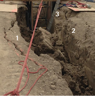
(1) Photos courtesy of author.
The results of the T-L method research concluded that worst-case soil exerts 68.75 pounds per cubic foot (pcf). It is common practice for rescuers to install 4- × 8-foot panels with two struts. Using that configuration, each strut supports a 4- × 4-foot area of trench wall behind each “half panel.” When 68.75 pcf is applied to that 4- × 4-foot (16 square-foot) area, we get a force of 1,100 pounds for each 16 cubic feet of soil.
Figures 1 and 2 show how the T-L Method determines the force of a failing section of soil that is being supported by panels and struts. Each photo shows these failures (in these cases, the fissures or tension cracks). The “SL” designations are abbreviations for the term “Simple L,” which is the distance measured in feet farthest from failure extent to the trench face. Note that, if no surcharge is present, the Simple L equals the total L or “L.” The drawings show the number of cubic feet contained in the failures that are pushing on the shoring system.
Figure 1. T-L Method: SL-1
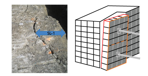
Each 4- × 4-foot section of panel as well as one strut is supporting 16 (4- × 4-foot × 1 foot) cubic feet of soil or 1,100 pounds of force. Since there is no surcharge, Total L is one or L-1.
Figure 2. T-L Method: SL-3
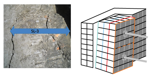
Each 4- × 4-foot section of panel as well as one strut are supporting 48 (4- × 4-foot × three feet) cubic feet of soil or 3,300 pounds of force. Since there is no surcharge, Total L is 3, or L-3.
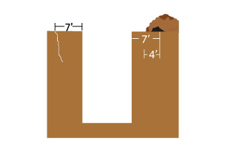
Photo 2 shows Simple L measurements on a real trench. Simple L is always the measure of the largest failure. In this case, although the trench has four different failures, the farthest distance from the trench face to a tension crack is 3 feet 4 inches. Always round up; in this case, Total L is 4, or L-4.
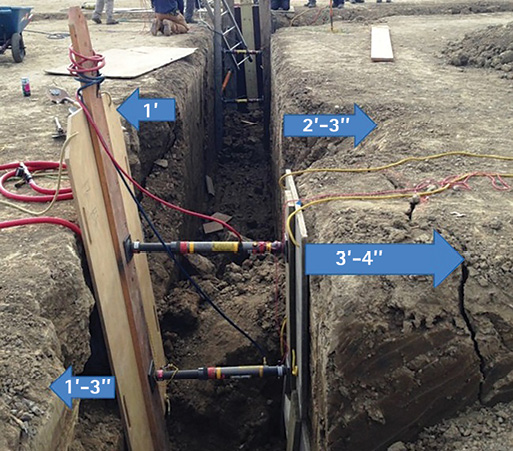
(2)
The second order of business for the USAR engineers was developing tabulated data for shoring equipment that is specifically designed for soil conditions found at trench rescue incidents. Using the forensic-based T-L method, group members Craig Dashner (P.E.), George “Donnie” Barrier (P.E.), and Dr. Janos Gergley (P.E.) tabulated data that is uniquely designed for trench rescue shoring operations. The design loads provide a minimum 2:1 factor of safety for the worst-case active soil forces. To make things easier for first responders, the factors of safety are always included in the tabulated data.
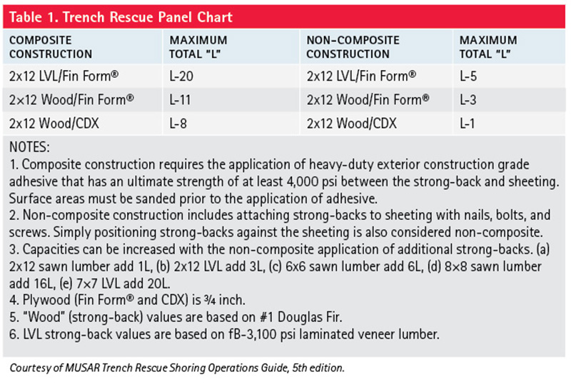
Using the tabulated data from page 14 of the MUSAR Trench Rescue Shoring Operations Guide, 5th edition (Table 1), we can determine which panel and strongback configurations will safely support a determined Simple L. For the L-3 trench in Figure 2, all panel assemblies listed, except the non-composite ¾-inch CDX plywood with 2- × 12-inch wood strong-backs, are strong enough to support this small load (3,300 loads per 4- × 4-foot section of shoring).
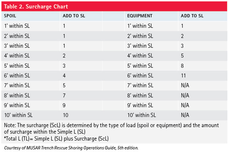
When heavy objects or piles of soil are close to the trench lip and/or within 12 feet of the shored area, they can cause additional pressure on the shoring system; those loads are called “surcharge loads.” Typical surcharge loads can include spoil piles, pipes, and heavy equipment such as excavators, loaders, and backhoes. The additional force from surcharge loads must be accounted for in the selection of the shoring equipment. The T-L method allows first responders to safely determine and add surcharges (ScL) to the Simple L (SL) to determine the Total L (L).
Surcharge L (ScL). Additional surface loads that are within the area between the original trench faces and the farthest point of soil failure (Simple L) measured in feet perpendicular to the trench wall.
Total L (L). The Simple L (SL) plus the Surcharge L (ScL) if one exists.
In Figure 4, the spoil pile is three feet from the trench face (wall). The Simple L (the farthest extent of the failure) is seven feet (SL-7) from the trench face. Therefore, four feet of the spoil pile is within the Simple L, and that load must be added to the SL-7. To find out how much additional force this will exert on the shoring, look at the surcharge chart (Table 2). Under the SPOIL column, four feet within the Simple L and right next to that in the Add to SL column we see that we need to add 2 to the SL-7. In this case, the Total L is 9 (L-9). To determine an equipment surcharge load, we repeat this process using the “Equipment” column in Table 2.
Figure 3. How Simple L is Measured for Different Types of Failures
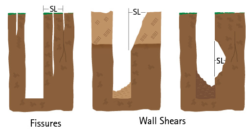
Figure 4. Surcharge Example
For the much less likely trench rescue incidents that do not involve any type of soil failure, an engineered conversion chart (Table 3) has been developed. The chart uses a correlation between the trench depth and the farthest extent of potential soil failures.
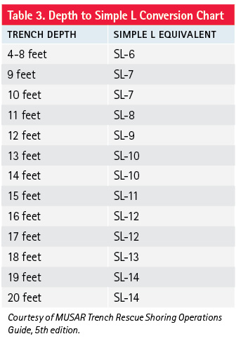
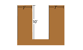
In Figure 5, there is no evidence of a soil failure. To determine the converted Simple L (SL), we need to measure the depth of the trench and then refer to Table 3. In this case, we find the trench depth (10 feet) in the “Trench Depth” column and follow that row to the Simple L Equivalent column where we find that the Simple L is 7 (SL-7). If there is no surcharge load, the Total L is 7 (L-7). If there is a surcharge load within 7 feet of the trench wall, then we would use Simple L-7 and repeat the process shown in the example above.
Figure 5. Depth Conversion Example
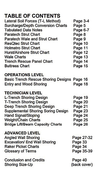
By using the existing soil failure evidence and the worst-case soil properties that are incorporated in the T-L Method, an accurate and reliable soil force can be determined. To make that determination, first responders only need to determine the Total L and then refer to the associated tabulated data to select the shoring designs and equipment needed to efficiently make the rescue area safe. The tabulated data included in the MUSAR Trench Rescue Shoring Operations Guide includes the items listed in the Table of Contents (Figure 6).
Figure 6. Table of Contents—MUSAR Trench Rescue Shoring Operations Guide
Trench Rescue Shoring Requirements
There is much confusion in the fire service generated from a lack of engineering principles designed for shoring soil failures and subsequent collapse conditions. Some strut manufacturers have added to that confusion by giving guidance for shoring soil that is “at rest.” In that guidance, it is usually mentioned that panels are only needed to confine the soil if signs of soil movement are present. They typically mention only two—sloughing and raveling—of several possible signs of soil movement. They also fail to mention other signs such as fissures, bulging, and subsidence and how arriving on scene to a collapse is a clear indication that the soil must be considered dynamic and unstable. As a result, firefighters have been taught to use shoring equipment that may support stable soil but cannot confine and support a significant soil failure.
Effective trench rescue teams do not carry a variety of shoring equipment or use different shoring techniques based on soil types. Instead, effective teams use equipment and techniques designed to handle worst-case soil conditions and learn how to apply it to all incidents. The goal of every trench rescue team should be to become proficient at installing shoring equipment in all typical trench shapes, depths, and widths with all the common soil failure void patterns. That goal can be achieved and begins with the following guidance.
To ensure that victims and rescuers are protected from progressive collapse, the trench rescue shoring system must use equipment that will collect/confine, transfer, distribute, and resist a minimum of twice the potential soil forces of worst-case soil conditions.
Collect/confine loads. The only way to ensure that the soil will be confined is to always use strong panels and close sheeting (panel edges touching or overlapping).
The strength of panels is dependent on the type of plywood and strong-back used and the method used to attach the strong-back to the plywood. Species of wood, density, and thickness are important. [Best practice: Fin Form® (¾-inch thick or greater) and laminated veneer lumber (LVL) (2- × 12-inch or greater) strong-back composite panels are the only panel construction that will provide a 2:1 factor of safety in worst-case soil conditions as determined using the T-L method.]
Transfer loads. Struts and wales are used to transfer loads (soil forces). Struts are used to stabilize a trench wall by transferring the load from the trench wall to a suitable point of resistance (commonly the opposing wall). Pneumatic and hydraulic struts are typically used by trench rescue teams. Use of timber struts is less common but still exists. Wales transfer the loads along the trench wall to the supporting struts. Wales are typically used to span large areas of trench walls without the use of intermediate struts. Wale sizes of 6- × 6-inch and 8- × 8-inch are commonly carried by trench rescue teams because they are light enough to allow for manual installation. [Best practices: Struts that can be installed and removed from outside of the trench (nonentry shoring) have measurable and controllable activation forces (900-1,250 pounds) and have the capacity to safely support soil forces up to 22 kips (pounds of force). LVL wales that are 7- × 7-inch are superior to common sawn lumber from both a strength (capacity and consistency) and longevity perspective.]
Strut activation forces. The installation of struts creates forces on the trench walls. In her research on “Earth Pressure Determination in Trench Rescue Shoring Systems,” LaBaw determined that excessive strut activation forces (3,000 pounds and greater) can cause, rather than prevent, soil failure and trench wall collapse. Excessive strut pressure is especially problematic in unstable and active soil conditions. On the other hand, the MUSAR Training Foundation has conducted destructive equipment tests that show that insufficient strut activation forces result in decreased beam (wale and strong-back) strength. LaBaw’s research, combined with the MUSAR Training Foundation, makes it clear that too much strut pressure can cause a trench wall collapse but too little strut pressure can result in premature shoring equipment failure. A good balance between those two extremes is strut activation forces of 900-1,250 pounds of force (0.9-1.25 kips). To determine how much strut activation force you are using, measure the internal diameter of the strut in inches and use this formula to find the area: p × (diameter/2)2. Then, multiply the area by the pneumatic or hydraulic pressure on your equipment gauge.
Example 1: Strut Diameter @ 2.5”/Pneumatic Pressure @ 200 psi
(2.5/2) × (2.5/2) × 3.14 = 4.9in2
4.9in2 × 200 psi = 980 pounds of strut activation force
Example 2: Strut Diameter @ 2”/ Hydraulic Pressure @ 1,500 psi
(2/2) × (2/2) 3.14 = 3.14in2
3.14in2 × 1,500 psi = 4,710 pounds of strut activation force
Distribute loads. The loads that are collected from a trench wall and transferred by struts must be distributed across a large surface area as they reach the opposing trench wall. Composite panels are strong enough and ductile enough to adequately distribute those loads. Without panels, loads transferred across a trench by way of struts reach the opposing wall and are only distributed across a small area (commonly 6- × 6-inch strut base, or 36 square inches). If that same strut is centered on a 4-× 4-foot composite panel, the load is essentially distributed over 2,304 square inches. The collected load of a failing trench wall can easily create thousands of pounds of force. If we consider a small section of failing wall in an L-3 trench (48 cubic feet, or just under two cubic yards), there is 3,300 pounds of force being transferred through the strut. When that load is distributed across a 4- × 4-foot section of composite panel, the load is reduced to less than 1.5 pounds per square inch. When that same amount of force is distributed across a 6- × 6-inch base, the opposite trench wall experiences more than 90 pounds per square inch. The strut base’s small surface area creates a highly concentrated load. The soil reaction to highly concentrated loads is to push back with an equal force in the opposite direction. Without a panel to confine that reaction, the soil pushing back will move, collapsing into the trench. (Caution: As described in NFPA 1006, spot shoring fails to meet the confinement and load distribution requirements needed to protect rescuers and victims in the most common trench rescue soil conditions. Furthermore, spot shoring in those soil conditions is not condoned or recommended by any of the rescue strut manufacturers. Of particular note, spot shoring is not compliant with modern geotechnical engineering principles and practices.)
Resist loads. Filling in or backfilling voids that have been created because of cave-ins is a necessary practice for shoring partially collapsed trench walls. An adequately backfilled trench wall will add strength to the point of resistance and reduce stress on shoring components. Whenever a strut interfaces with a trench wall or trench floor (raker) at an angle of less than 70°, artificial resistance (a 2:1 factor of safety) must be added. (Best practice: Backfill techniques include air bags, soil, wood, backshores, and buttresses. Pickets and counterweights are commonly used methods of artificial resistance.)
The theories and typical soil pressure diagrams used by OSHA, strut manufacturers, and many civil engineers do not account for soil failure and trench wall collapse, which are the prevalent conditions at trench rescue incidents. The tabulated data, shoring designs, and practices associated with those theories are not relevant to trench rescue shoring operations.
With a fundamental understanding of the T-L method, the associated tabulated data, and safe trench rescue shoring requirements, firefighters can finally rely on science to select and use safe and efficient shoring equipment and techniques for both the more frequent collapsed soil conditions and the occasional trench incidents without soil failures.
Reference
Taylor O and M LaBaw. “Emergency Trench Shoring and Rescue: A Simplified Method for Calculating Lateral Earth Pressures.” Advances in Civil Engineering, Volume 2018. Article ID 5280926.
OLIVER-DENZIL TAYLOR is a licensed professional engineer (MA #48116) and a board-certified ASCE Academy of Geo-Professionals diplomate of Geotechnical Engineering (D.GE #1454). He has worked as a senior researcher (geotechnical) in U.S. Army Engineer Research and Development and has served as a structure specialist for the U.S. Army Corps of Engineers and Tennessee Task Force 1 Urban Search and Rescue. Taylor has authored more than 90 technical publications related to soil behavior, earned his M.Sc. and Ph.D. in civil engineering from the University of Rhode Island, and is a graduate of the University of Salerno’s (Italy) Landslide Risk Assessment and Mitigation program.
S. MARIE LaBAW is a licensed professional engineer (MD #33334) with the Office of the Fire Marshal in Montgomery County, Maryland, and a structures specialist for Maryland Task Force 1. She has five years of experience as a firefighter and 22 years of engineering experience, 18 of those focused on emergency operations. She has provided engineering support on both local and national incidents including multiple line-of-duty death investigations, hurricane responses, and building collapses. She earned her MS and Ph.D. in civil engineering from the University of Maryland.
RON ZAWLOCKI is a 49-year fire and rescue service veteran who serves as a rescue team manager with Michigan’s Urban Search and Rescue Task Force. Zawlocki has shored more than 1,000 live trenches and has pioneered the destructive testing of trench rescue shoring systems to validate factors of safety. He has taught fire and rescue courses throughout the United States, Canada, Mexico, and the Middle East for more than three decades and has developed several technical rescue training programs, coauthored the book Trench Rescue: Principles and Practice for NFPA Standards 1006 and 1670, and authored course textbooks as well as articles that have been published in national fire and rescue service magazines.

