By RON ZAWLOCKI
Almost four decades ago, James Gargan—“The Godfather of Trench Rescue”—developed techniques to make firefighters safer at trench rescues. Prior to that, firefighters would typically enter trenches and dig out trapped victims without any protection from trench wall collapse. His experience and training in construction safety came from working as an operating engineer, and his trench rescue shoring practice appears to have been taken loosely from the Occupational Safety and Health Administration’s (OSHA’s) construction shoring charts.
- Trench Rescue: Controlling Soil
- TRENCH RESCUE: THE BASICS
- TRENCH RESCUE LESSONS LEARNED
- Trench Rescue Shoring: “Our Dirty Little Secret”
Over the past few decades, many firefighters have continued to follow Gargan’s shoring guidance, while others have “invented” their own shoring designs, equipment, and techniques. As a result, many shoring designs and techniques have gained acceptance within the fire service without being subjected to scientific testing or an engineer’s review. The current litmus test for acceptable trench rescue shoring practices seems to be the following:
- Digging a trench,
- installing shoring,
- observing the trench walls and shoring, and
- drawing conclusions from the observations.
This process typically takes place during training sessions, where the soil conditions are stable and static, resulting in little or no lateral soil forces on the shoring systems. After this process has been repeated several times without an observed collapse, firefighters typically conclude that the shoring designs, equipment choices, and techniques are safe. However, the stable and static soil conditions that have typically been used during this unscientific process were not going to collapse, regardless of what was done to it. Without the use of instruments (load cells) to measure the forces that are being placed on the shores, we cannot draw any accurate or meaningful conclusions to determine any level of safety (factor of safety). By associating the unmeasured performance of shoring in stable and static soil conditions to the effectiveness of that shoring in the unstable and dynamic soil conditions found at most trench rescue incidents, firefighters have created several trench rescue shoring myths.
Myth or Science?
This article will expose some of the myths of soil concepts and shoring methods that have spread through the fire service but are not actually based on geotechnical and structural engineering principles and practices and will define myth and science as follows:
- Myth: Widely held but false beliefs of ideas.
- Science: The use of theoretical behavior and empirical data confirmed by testing that leads to solutions.
Some of these myths have resulted from first responder attempts to resolve trench shoring issues without the use of any engineering analysis, while others have resulted from the application of theories and methods that were developed for deep excavations soil retention construction projects rather than for the shallow braced (shored) trenches that are most common at trench rescue incidents.
Unfortunately, deep excavation soil theories and the application of many construction-based shoring methods are not applicable to most trench rescue shoring situations. As a result, many of the current trench rescue shoring practices now in use are not “best practices,” while others are simply just dangerous. In her research of trench rescue shoring principles and practices, Dr. Marie LaBaw concluded that there has been a lack of engineering analysis for trench rescue shoring and that deep excavation construction-based shoring is significantly different from trench rescue shoring.
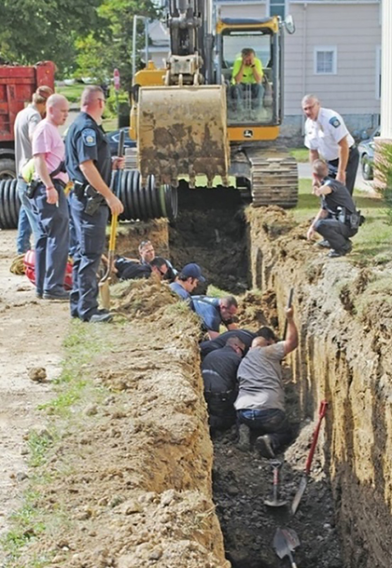
(1) Although it is not as prevalent today, firefighters still “jump into” trenches with no protection from collapse. [Photo by Times Gazette (Hillsboro, Ohio).]
In 2017, I was invited to participate in the development of a trench rescue course designed specifically for the professional engineers who are structures specialists with urban search and rescue (US&R) task force teams in North America. The course has since been presented as part of the Federal Emergency Management Agency’s US&R Structures Sub-Group Regional training curriculum. The team that developed the course included Oliver-Denzil Taylor, PhD, P.E.; Marie LaBaw, PhD, P.E.; Janos Gergely, PhD, P.E.; George “Donnie” Barrier, P.E.; Craig Dashner, P.E.; and me. Following the development of the course, this team has continued to work together to enhance rescue shoring practices by using engineering principles and current equipment and materials.
Taylor and LaBaw have provided geotechnical principles (science) that expose and dispute some soil-related myths that have spread throughout the fire service, while Dashner, Barrier, and Gergley have provided engineering principles and fundamental physics (science) that expose and dispute some shoring design and equipment myths that have gained acceptance within the fire and rescue communities. It is our hope that the methods, principles, and practices presented in this article will dispel the myths and initiate a much-needed shift in the trench rescue shoring paradigm, replacing them with engineered principles and practices designed specifically for trench rescue conditions.

(2) The orange “X” shore has been used more than 70 times without any collapse. Repeated use alone does not prove that something is safe. (Photos 2-10 by author.)
Soil Myths and Science
Properly conducted soil exploration and classification analysis can help trained and experienced professionals determine behavioral information—i.e., relative soil strength, stability, and lateral soil forces. Most trench rescue courses mention the OSHA soil classification method (Type A, B, and C soils) but do not provide enough practical behavioral information to be of any value. The myth would have us believe that, under the pressures of making time-sensitive decisions, firefighters with limited training, practice, and equipment can correctly quantify the soil strength, stability, and lateral soil forces needed to safely shore a collapsed trench by using the OSHA method of classifying soils.
We can better understand the intent and purpose of the OSHA soil classification method by looking back five decades ago, when OSHA 29 CFR Subpart P was developed with the purpose of improving the safety of construction workers who work at trench and excavation sites. The shoring section of the standard was created for use by construction workers who are on site during the excavation process and can install shoring during (shoring in lifts) and shortly after the digging is completed. However, the OSHA standard does not address rescue operations at trenches or excavations and gives no guidance for shoring the unstable, dynamic, and failed (collapsed) soil conditions that are associated with trench collapse rescue incidents.
Following is a short synopsis of the evolution of OSHA soil classifications. It, along with the science presented below, will help you understand why using OSHA soil classifications and associated tabulated data is not the best practice for rescuers.
In 1971, OSHA promulgated its excavation standard. In that standard, soils were classified into three types: running, unstable, and hard compact. These terms were generally misunderstood. Later, the terms were revised and renamed granular, cohesive, granular cohesionless, and cemented.
In 1989, OSHA revised the standard and included the following requirements: Classification of soil and rock deposits. Each soil and rock deposit shall be classified by a competent person as stable rock or Type A, B, or C. Lateral soil forces were associated with Type A, B, and C soil based on a survey from construction workers and were not based on geotechnical engineering principles.
Note: In 1994, OSHA explicitly stated that the 29 CFR Subpart P, Appendix C and the equations presented in Table C-1.3 should not be used to determine lateral forces and design shoring systems.
Soil Classification Myths
Many first responders have adopted the OSHA method of classifying soil type mostly because it was readily available in the OSHA standard. Although most firefighters are made aware of the OSHA method in their trench rescue courses, very few receive enough training and recurring experience using it to be considered a “competent person.” After 48 years of fire/rescue service, I do not know any firefighters (myself included) who can make accurate technical decisions about the soil or the shoring needed for collapsed trench conditions.
To comply with a standard that was never meant to provide trench rescue shoring guidance, many firefighters decided to streamline the OSHA soil classification process by considering C-60 soil as “worst case” and then began classifying all soils at trench rescue incidents as Type C-60. Several myths have resulted from attempting to use the OSHA standard for rescue operations.
Soil Classification Science
From a practical perspective, first responders may take a class and receive an OSHA “Competent Person” certificate, but they simply do not get enough experience using the knowledge and skills to become qualified. For safety’s sake, we cannot rely on visual and manual tests conducted by first responders to produce meaningful trench shoring information. From an academic perspective, the equations presented in Table C-1.3 of the OSHA soil standard are based on overly simplified lateral earth-pressure principles that do not represent the manner on which soil imparts loads to the shoring in trenches (braced excavations), and the lateral soil forces associated with Type A, B, and C soils (A-25 psf, B-45 psf, C-60 and C-80 psf) are not based on accepted geotechnical engineering principles for excavations and retaining structures, which include shoring systems. The resulting OSHA soil classifications give only a broad estimate of lateral earth pressures, which are neither accurate enough for use by engineers nor safe enough for use by first responders at trench emergency incidents.
Recently, Taylor and LaBaw, both professional engineers with doctorate degrees in geotechnical engineering and structure specialists with the National US&R Response System, created a simple and accurate method specifically for first responders to effectively calculate the maximum lateral soil forces that can exist for collapsed trench and excavation walls. This method, called the “T-L method,” is based on the actual failure conditions found at the rescue site and not hypothetical conditions that exist only in textbooks, computer models, or ideal conditions. Paramount to this new method is the use of engineering principles that use all the worst properties associated with the 15 primary soil categories within the Unified Soil Classification System (USCS) to determine a true “worst-case” soil type. Inherent to the T-L method are the forensics-based principles that adjust the maximum potential lateral earth pressures to account for diverse soil characteristics, ground inclinations, the presence of soil spoil piles and heavy equipment, and varying moisture conditions without requiring the responders to have an intimate knowledge of soil mechanics. The result is a rapid and accurate method that allows first responders to determine lateral soil forces within minutes of arrival at a trench/excavation emergency by simply measuring the maximum failed dimension at the site.
The “one-size-fits-all” approach, which firefighters have adopted, considers soil conditions at all trench rescue incidents as Type C-60. It appears that this myth started after firefighters realized that, at trench rescue scenes, they had neither the time needed to conduct OSHA-recommended soil testing nor the training and experience to do so properly. With that in mind, firefighters applied deductive reasoning and concluded that the shoring equipment used at trench rescue incidents needs to be strong enough to resist worst-case lateral soil forces. The logic is that shoring equipment and the shoring designs that are safe for use in the worst-case soil conditions would also be safe for any other soil condition. However, the first flaw in that logic resulted from the fact that modern geotechnical engineering principles were neither used to determine the properties of Type C-60 soil nor used to conclude that Type C-60 soil is the worst-case soil condition. Firefighters continue to use the one-size-fits-all approach despite an OSHA directive, which states, “OSHA does not regard the C-60 classification as including the ‘worst’ type of soil. If, therefore, a manufacturer’s tabulated data covers soil only through the C-60 classification, then the data does not cover all possible soil types. An employer who elects, for convenience’s sake, to treat the soil in an excavation as C-60 would still have a duty to ascertain that the soil is not, in fact, worse than C-60.” More importantly, as stated above, when geotechnical engineering principles are applied, Type C-60 soil does not provide an accurate lateral earth pressure determination for “worst-case” soils. Although Type C-80 soil carries a higher lateral earth-pressure calculation than Type C-60, neither of these sub-categories accurately calculates worst-case lateral earth pressures.
For a better understanding of how this myth evolved, consider the origin of the term “C-60 soil.” In 1989, OSHA revised the standard to require a competent person to classify each soil deposit as either Type A, B, or C. The subsequent Type A-25, Type B-45, and C-80 soil descriptions are not part of the OSHA standard but are referenced in the equations found in 1926 Subpart P App C. Type C-60 was promulgated by shoring manufacturers and is not part of the OSHA standard. The numbers attached to those descriptions are unscientific estimates of lateral earth pressures that have been advanced by shoring manufacturers and are not part of the OSHA standard. The shoring guidance found in the tabulated data provided by those shoring manufacturers often states that C-60 soil will stand long enough for shores to be installed and that in C-80 soil shores cannot be installed because the soil will fall in before it is shored.
Ultimately, firefighters have misinterpreted the concept, “Shores cannot be installed in C-80 soil because the soil will fall in before it is shored,” to mean that C-60 is the worst-case soil condition that would permit the use of shores. In reality, most trench rescue emergencies are the result of soil that had collapsed before shoring was installed. OSHA shoring guidance does not address those conditions. Rescuers must recognize that shoring trench walls that have collapsed is the essence of “trench rescue shoring” and must be a focal point of every trench rescue training curriculum.
So, what is wrong with using OSHA’s tabulated data or the tabulated data found in shoring manufacturer manuals? Simply put, the shoring guidance given by OSHA and much of the related tabulated data from shoring manufacturers is not meant for rescue operations, and attempting to apply it to rescue operations has resulted in misinterpretations and mistakes. Furthermore, the faulty assumption that Type C-60 soil is the “worst-case” soil condition has led to the misunderstanding that the shoring equipment and designs that have been engineered for C-60 soil conditions are appropriate and safe for what are actual “worst-case” soil conditions.
As stated above, OSHA does not recognize Type C-60 soil as the worst type of soil, and modern geotechnical engineering practices have shown that the process used to define the criteria for C-60 soil is not an accurate representation of worst-case soil. The fact is that none of the OSHA soil classifications provide a science-based method of calculating worst-case lateral-earth pressures and, therefore, we should not rely on the tabulated data that is based on the Type A-25, B-45, C-60, and C-80 lateral soil forces to determine shoring materials, equipment, and design requirements at trench collapse incidents. More importantly, the tabulated data that has been established for shoring equipment use in Type A, B, and C soil is not appropriate for use by first responders working in the unstable and dynamic (worst-case) soil conditions that are associated with trench rescue incidents. Although not all trench rescue incidents are the result of trench wall collapse, they are certainly the overwhelming majority.
Fortunately, tabulated data created specifically for worst-case (collapse) soil conditions and trench rescue shoring has been developed by Dashner, Barrier, and Gergley, who are also structure specialists with State Urban Search and Rescue Alliance teams. The combination of the T-L method and that tabulated data provides first responders with an engineered trench shoring methodology designed for the conditions we are confronted with at trench rescue incidents.
Soil Theories
Many trench rescue instructors have attempted to explain the effects of shoring on trench walls predominantly by using two hypotheses. These hypotheses are commonly referred to as “soil arching” and the “cone of pressure,” and their application to shoring unstable and active soil conditions has become a widespread myth. The following sections will explore the myths and provide the science (engineering principles) that are associated with these concepts.
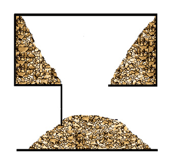
Soil arching and the cone of pressure hypotheses as depicted in photo 3 do not provide protection from collapse in the unstable and active soil conditions associated with most trench rescue incidents.
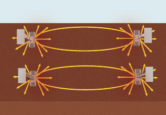
(3) The “soil arching” and the “cone of pressure” hypotheses, as depicted here, do not provide protection from collapse in the unstable and active soil conditions associated with most trench rescue incidents.
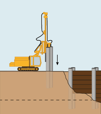
(4) The soldier piling and lagging process.
Soil Arching Myths
Some strut manufacturers and many trench rescue instructors have purported a correlation between soil arching phenomena as seen in rigid earth retention systems like soldier piling and lagging with the use of struts installed in columns (vertical alignments) as used in trench collapse condition. Although empirical evidence of soil arching exists when rigid retention systems are installed in competent soils, there is no academic or empirical evidence to support the idea that soil arching can be relied on to prevent or minimize collapse when the soil is unstable and active.
This myth has led to some dangerous practices such as shoring unstable soil conditions without panels and shoring unstable soil conditions with panels that are not strong enough to provide a minimum 2:1 factor of safety when used in those conditions.
Soil Arching Science
As shown in photo 4, soil arching is an observed phenomenon associated with the use of a rigid soil retention system, known as soldier piling and lagging. Soil arching is explained and scientifically observed through a simple procedure called the “trapdoor experiment,” as shown in photos 5 and 6. In this experiment, a box is filled with soil and has a “trapdoor” on the bottom. If the soil is intact, the soil has sufficient strength (effective internal friction angle and effective cohesion) and, if the size of the door (the distance between supports) is not too large, the soil particles will move toward each other to create an arch. However, if the soil is not intact to begin with; the opening (distance between supports) is too large; or, the internal strength of the soil is insufficient, a very large amount of soil will fail and pour out through the opening. If you are thinking, “That’s a lot of ‘ifs,’” you are correct. The problem is that there is no scientific means to predict if a small failure or a very large failure/collapse will occur. Determining the shear strength of the soil and the spacing of the supports that would result in soil arching is way beyond the capabilities of first responders.
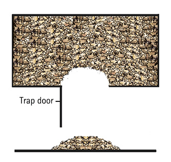
(5) When the soil is “competent” and the opening (the space between supports) is not too large, the soil moves and falls out of the opening until an arch is created that stops more soil from moving.
(6) If the soil is not competent enough to create an arch or if the opening is too big, a very large amount of soil will fall (collapse).
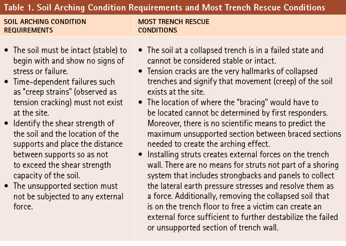
For soil arching principles to be effective, all the following conditions must exist:
- The soil must be intact to begin with and show no signs of stress or failure.
- The unsupported section cannot be too large that the shear strength of the soil to either side of the opening is not exceeded.
- The unsupported section is not subjected to any external force.
- Time-dependent failures such as “creep strains” (observed as tension cracking) do not exist at the site.
None of the required conditions listed above can be guaranteed at a trench collapse incident. Therefore, soil arching and the shoring techniques that rely on soil arching should not be used at trench collapse situations.
If and when soil arching occurs, it does not prevent the movement of the soil between the supports. In fact, for soil arching to occur, soil movement is required. In photo 7, the areas between the red lines (arch) and the trench wall are subject to collapse. Shoring techniques that do not use panels in close sheeting configurations (spot shoring and skip shoring) do nothing to prevent the soil in those areas from falling into the trench. The soil falling into the trench between supports can be in quantities large enough to injure or possibly kill the rescuers and trapped victims.
We cannot determine the location of the supports from field observations, and there is no scientific means to predict the maximum spacing between supports needed to create the arching effect. With that said, there is no reliable means available for predicting a reduction in lateral earth pressure attributed to soil arching between supports. Therefore, we should use closed sheeting with shoring equipment and materials capable of resisting the lateral soil forces of worst-case soils with a minimum 2:1 factor of safety at all trench rescue incidents.
When the requirements for effective soil arching are compared to the conditions that exist at most trench rescue incidents, it becomes apparent that relying on soil arching to prevent collapse is a dangerous proposition (Table 1).

(7) Relying on soil arching to prevent collapse is a dangerous proposition.

(8) The cone of pressure hypothesis is not in line with the fundamental physics reality that, “Every action has an equal and opposite reaction.”
“Cone of Pressure” Myths
The fire service has embraced an unproven theory that suggests strut activation force creates a four-foot-diameter (cone-shaped) area of pressure on the trench wall, which compacts and stabilizes the soil within the “cone” and prevents soil from moving in the direction of the trench face. Photo 8 depicts this hypothesis. However, the hypothesis fails to apply a fundamental rule of physics that states, “For every action, there is an equal and opposite reaction.” Simply, if we push on the soil, it pushes back, and the harder we push, the harder the soil pushes back. Relying on the “cone of pressure” to prevent collapse is a dangerous proposition.
“Cone of Pressure” Science
Struts are installed in trenches under pressure. That pressure usually results from pneumatic, hydraulic, or mechanical (wedges or screw jacks) means. The pressure applied multiplied by the surface area of the strut creates a force—the “strut activation force”—that pushes on the trench wall (the face). Research shows that strut forces distribute into the soil in the shape of a half ellipsoid firefighters call “the cone.” The soil then reacts by pushing back toward the trench face at a greater diameter than the diameter of the force pushing in (the strut load).
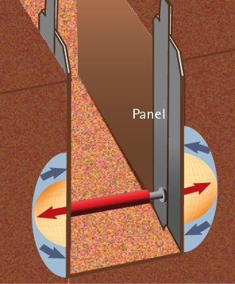
(9) When the force is distributed across a panel, the pressure [pounds per square inch (psi)] is reduced. The reaction (pressure pushing back) is also reduced and can be resisted by a “premium quality” panel.
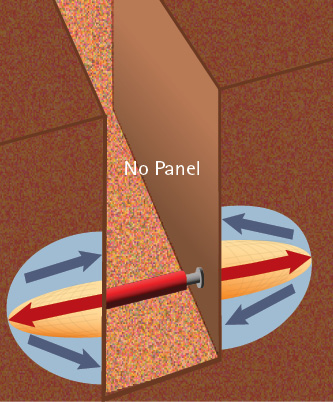
(10) When the force is not adequately distributed (no panel/strongback), the psi pressure is much higher and the reaction pressure (pushing back at the trench wall) is also higher. Compounding that problem is that, without a panel, there is nothing to resist the pressure, and a “spot shore” can create, rather than prevent, a collapse.
As seen in photo 9, when a panel such as a four- × eight-foot FinnForm (an expensive plywood from Finland) panel and two- × 12-inch strongbacks are placed between the strut base and the trench wall, the strut force is distributed and does not penetrate the trench wall as deeply, causing minimal soil movement toward the trench face. As shown in photo 10, when a panel is not used, the strut forces push farther into the trench wall, causing significantly more soil movement toward the trench face. These drawings are based on research conducted by LaBaw, who concluded that soil reacts to strut forces by pushing back in the direction of the trench face, which, without the use of strong panels, is more likely to result in collapse rather than preventing a collapse in unstable soil conditions. There is no geotechnical, academic, or empirical evidence that supports the myth that struts provide a “cone of pressure” that stabilizes a trench wall or prevents collapse.
Permanent soil retention systems and shoring at planned excavations are significantly different than trench rescue shoring. Many of the theories, formulas, and soil analysis practices that are applicable for construction-based soil retention systems are not applicable for rescuers shoring shallow trenches and excavations (less than 20 feet deep) with failing soil conditions.
RON ZAWLOCKI began his fire service career in 1974 with the Detroit (MI) Fire Department. In 1977, he joined the Pontiac (MI) Fire Department and retired in 2007 as its battalion chief. He is also a rescue team manager with the Michigan Urban Search and Rescue Task Force 1. Zawlocki has served on local, state, and national committees on firefighter safety and technical rescue. He has pioneered the destructive testing of trench rescue shoring systems to validate factors of safety. Zawlocki has a bachelor’s degree in secondary education and has taught fire and rescue courses throughout the United States, Canada, Mexico, and the Middle East for nearly three decades. He has also developed several technical rescue training programs, co-authored the book Trench Rescue- Principles and Practice for NFPA 1006 and 1670, authored course textbooks, and been published in national fire/rescue service magazines.

