By Mike Donahue
There’s one portion in the discipline of rope rescue that I think is overlooked and, honestly, fascinating: The physics behind everything we rig. Understanding what systems to build to when to build them is one thing, but there’s more to these choices. When I first began studying rope rescue, I was provided a solid foundation on which I could build. I’m never really satisfied with what I know; I always want to know more. It wasn’t until I became interested in the physics behind what we do that I realized what I had been missing.
Physics plays the most vital role in our rigging operations; it’s the true safety factor within we must work. The recommendations that National Fire Protection Association (NFPA) 1983, Standard on Life Safety Rope and Equipment for Emergency Services, provides are what is “drilled” into our heads from day one. How many times have you heard we must operate with or within a 15:1 system safety factor (SSF)? A lot.
The 15:1 SSF is kind of a “myth” or “legend.” We never operate in that 15:1 window. Once a knot is loaded in a system, you’ve lost your numbers. However, this is not a big deal. NFPA provides that 15:1 SSF as a recommendation. As a knowledgeable rescuer, you can rig with whatever SSF your setup equates to and still be safe. When it comes to physics, there’s no defeating it; as a rescuer, you need to respect and understand it. Not understanding the physics behind what you’re building would be the equivalent of a firefighter pushing a line into a fire without any understanding the dynamics of fire. You, can, however, manipulate physics using other physics. In this article, I want to scratch the surface of the physics you work with and help you understand how to make the laws of physics work for you.
Rope work is a constant battle with gravity. The systems and devices you use control and manipulate gravity to work FOR you. With that being said, unless you know and understand the physics you’re manipulating, you could find gravity quickly working against you.
I will begin with our main concern in rope work—load force. Load force is the force exerted through the ropes, components, and the anchor created by the load. The load force and the angles through which you force it is called “vector force,” which is found in an angle that is trying to simultaneously pull vertically and horizontally. This force creates a multiplying effect when the load force meets the angle. Because you work with angles in rope rigging, vector forces are ever present. You must understand which forces are being generated and how they are generated.
The commonly used load sharing anchor system shares the supported load. As the angle of the system increases, the force that the anchors see increases. This refers to vector forces; we’re all taught several different degree benchmarks that would estimate the load force being generated by the vector force. But how about when we’re outside of those benchmarks? There’s something to be said for pinpoint accuracy.
Three things you need to know and understand follow:
- The anatomy of a right triangle,
- a sine, and
- a cosine.
Figure 1 shows the anatomy of a right triangle. This is important to know because it is based on the angle and load force you are working with, and sine and cosine will be determined by this.
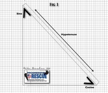
Figure 2 explains when to use sine and or cosine.
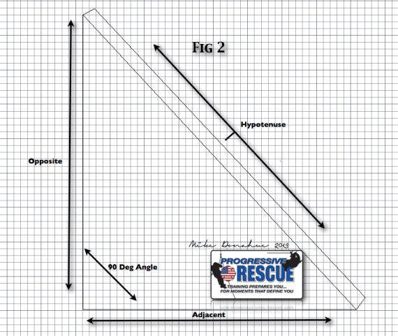
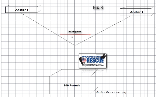
Figure 3 refers to the load sharing anchor system. Place the center point of a protractor where the two legs of the load sharing anchor system meet. This should measure 150°. The goal here is to find out what load force each line in this anchor system sees. When it comes to forces, I am concerned about all the components in the system, not just one. The components in a system don’t always all have the same load rating, therefore, they will be affected differently. Generated force uses the rope as a “road” traveling from the anchor to the load, affecting all in its path.
To calculate these forces, the decision to use sine (sin) or cosine (cos) is based on the relationship of the desired angle in relation to the hypotenuse of the created triangle. Cosine (cos) is used when calculating the vector force on a angle created adjacent the hypotenuse, whereas sine (sin) is used for an angle opposite the hypotenuse. For a load sharing anchor system with mirrored degrees on either side, use either sine or cosine.
In Figure 3, you must calculate how much load each half of the system sees. Therefore, cut the load and angle in half. Below is a breakdown of the formula. This may not be its exact mathematical depiction, but I believe this is easier to understand.
- Step 1: The angle is 150°. One-half of that is 75°.
- Step 2: The load is 500 pounds. One-half of that is 250 pounds.
- Step 3: Using a calculator, input the number 250 and then divide that by the cosine of 75°, and your answer should be 965.9258262872797475 pounds. (For this article, let’s round up to 966 pounds.)
This formula tells us how much weight is actually on each leg of the anchor system; no estimating, just pinpoint numbers. Write down this formula on a card and keep it in a calculator in your gear bag.
Another rigging technique we use often is a directional pulley (Figure 4). However, most of us never consider the loads that are being or going to be applied to the anchor and the hardware.
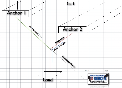
As before, there’s a mathematical equation you can use to calculate the forces hitting that anchor and hardware. It’s similar to the previous equation, so you first must look at your load.
In this example, let’s use an 800-pound load. Next, decipher what the created angle is; an oversized protractor works great for this. Let’s work with a 110° angle. Once we have that information, grab the calculator and a pen and paper.
Following is a breakdown of the equation:
- Cosine of half the angle × 2. This step is slightly different than the one above because you must input Cosine and 55 into the calculator. Then, take that number and multiply it by two. The resulting answer is read as a percent.
- Take the calculated percent and multiply by the load.
The resulting answer will be the load force the anchor and hardware will see.
Following are the above steps used in the calculation:
- Cos 55 = 0.573 × 2 = 1.14 or 114 percent.
- 800 pounds × 1.14= 912 pounds.
Answer: The directional anchor and associated hardware is seeing a load of 912 pounds.
Calculating actual load forces in a system isn’t difficult. Like anything else, you need to practice these equations to become proficient in them. Being able to produce pinpoint load numbers in a system is not only helpful but could be paramount. A good rescue specialist presents facts at an operation, not estimates.
 Mike Donahue has 17 years of fire service experience and has been a career firefighter in the city of Elizabeth, New Jersey, for the last 13 years, working out of Rescue Company 1 for the past 10 years. Mike teaches a Middlesex County College as an adjunct professor and acts as the fire service program coordinator. Mike is the owner of Progressive Rescue and can be reached at progressiverescue@gmail.com.
- Sloped Floor Shoring Systems
- A Common-Sense Approach to Technical Rescue
- Rigging for Horizontal and Vertical Confined Space Entry
- Tech Rescue: Shoring Operations
- Size-Up and Plan Development at a Technical Rescue Operation
- Rigging Outside the Box

