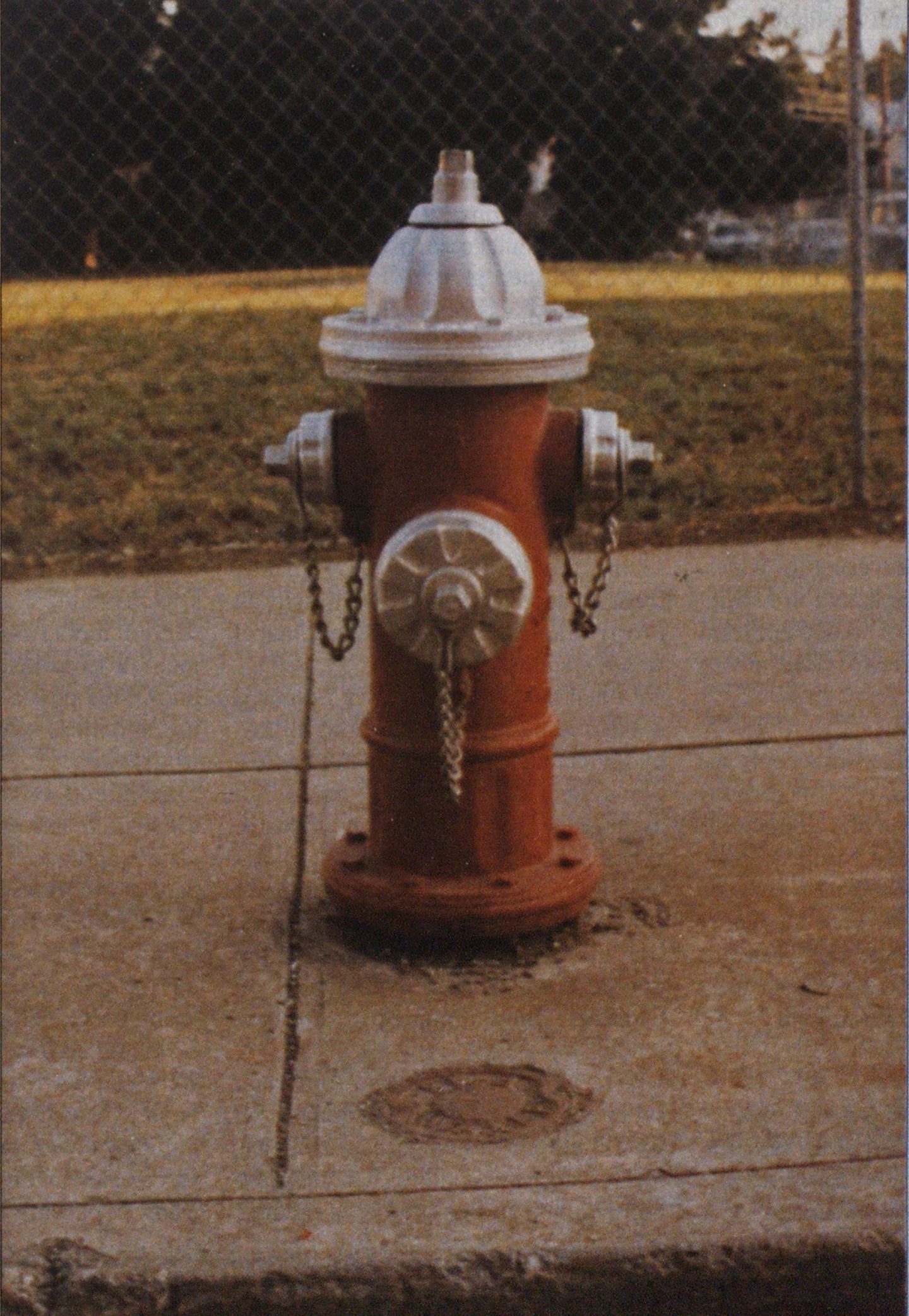
The Fire Hydrant
EQUIPMENT
This vital piece of fireground equipment is too often taken for granted, but demands a much closer look.

Since the earliest days of organized firefighting, the success or failure of fireground operations has hinged on the ability to obtain and deliver sufficient quantities of the extinguishing agent, primarily water. In response to water supply problems, extensive central water systems have been developed, and the fire hydrant has become the firefighter’s means of accessing the water system and controlling water flow.
The original water mains were often constructed of wood. The hydrant was nothing more than a plug that was driven into a hole, and firefighters accessed the water supply by removing the plug and quickly inserting a suction hose into the hole. With the development of cast-iron water mains in the mid1800s, the most common hydrants were cast-iron standpipes rising two or three feet above ground level, with one or more nozzle outlets protruding from them. No provisions were made for controlling the flow’ of water or protection from freezing. In the latter part of the century, hydrants began to evolve into the basic configuration with which we are so familiar today.
Fire hydrants are as important to the water system as the reservoirs feeding it or the w ater mains delivering the water. It would be ludicrous if, at a fire structure requiring a flow of 10,000 gpm and surrounded by a system of w ater mains capable of flowing 12,000 gpm, there were an inadequate number of hydrants capable of flowing 600 gpm each. Fire hydrants that are poorly located, inoperable, or too small to provide large volumes of water, or that have not been properly maintained, can give a false sense of security.
Hydrants are as critical to the water system as the reservoirs and water mains that support it.
APPLICABLE STANDARDS
The first nationw ide standard for the uniform manufacture of fire hydrants was established in 1913 by the American Water Works Association (AWWA), which developed a standard for wetbarrel hydrants. This has evolved into AWWA Standards C502 and C503, covering both wetand dry -barrel hydrants. AWWA Standard C600 offers guidelines for the proper installation of fire hydrants and their appurtenances. These standards cover the design, flow characteristics, and manufacture of virtually all fire hydrants now used in municipal water systems.
Underwriters Laboratories Standard #246 outlines the specifications for fire hydrants that are part of the fire protection system of private water lines, such as those for large buildings and industrial complexes. Such hydrants are similar to AWWA hydrants, but incorporate additional features beneficial to industrial fire protection that would be impractical or unnecessarily expensive on hydrants within a municipal water system.
The NFFA publishes two important standards pertaining to hydrants and water systems. Standard #291 describes suggested practices of flow-testing hydrants and color-coding them to indicate available water flow. Standard ‘ #24 outlines recommended installation practices.
There is a wealth of information available that will provide the fire officer with the proper guidelines when working with municipal planners in the improvement or development of new water systems.
HYDRANT DESIGN
The modern fire hydrant has evolved into a carefully engineered yet rugged piece of equipment. Some important design criteria of a hydrant are protection from the elements (primarily freezing), ease of operation, the ability to operate properly with minimal maintenance, and ease with which it can be” repaired without actually replacing it. The modern AWWAor U/L-approved hydrant is designed to comply with all: of these criteria.
A fire hydrant is limited in the quantity of water it is able to deliver by the capacity of the water mains supplying it. The water mains supplying water for domestic needs are usually the same lines used to provide water for fire protection; a branch line is run off of the main line to supply the hydrant. This line should be a minimum of six inches in diameter, but an eight-inch-diameter line is called for at locations where unusually large flows are required or where the hydrant is situated a significant distance from the main. Many older systems and some improperly engi-^ neered modern systems have a fourinchor even three-inch-diameter feed lines. This puts a severe restriction on the amount of water the hydrant is able to deliver.
A shut-off valve is located between the hydrant and the main to control the water supply to the hydrant for maintenance and replacement. It is usually located within ten feet of the hydrant. A shaft called a valve box is situated on top of the valve and extends up to ground level. The top of this shaft can be identified by a round metal lid about six inches in diameter with the word “water” usually cast on its face. Removing this cover permits access to the valve below, w hich can be operated by using a specially designed wrench. For the hydrant to be in service, this valve must always be fully open.
Photos by author.

Two types of hydrants, wet-barrel and dry-barrel, are manufactured to suit warm and cold climates, respectively. The wet-barrel hydrant, in which the entire assembly is always charged with water, is used in regions where there is no danger of freezing. Where the temperature goes below freezing, a drybarrel hydrant is used. The water in such hydrants is kept below the frost level until the hydrant is opened.
In dry-barrel hydrant operation, the water enters the hydrant through a 90degree bend called the shoe, where it changes direction upward. Immediately above the shoe, the water reaches the main valve, which controls the flow of water into the barrel and is a primary determinant of the gpm that can be delivered. This main valve is usually four to six inches in diameter. It is made of neoprene (depending on the manufacturer, it may have a steel insert for reinforcement), and provides a watertight seal against a bronze seat. The operating stem extends from the main valve upward through the top of the hydrant. The uppermost portion of the valve stem is the operating nut, to which the hydrant wrench is applied. Turning the operating nut in the proper direction pushes the main valve down off of the seat, allowing water to enter the barrel as it flows around the main valve and into the main barrel. Care must be exercised when opening the hydrant that the stem is being turned in the correct direction; a directional arrow, indicating the direction for “open,” is cast on the top of all modern hydrants.
The water enters the barrel and is then discharged through the nozzle openings. Great care is taken in hydrant design to minimize the friction loss around the main valve and in the areas where the nozzles protrude into the upper barrel section. AWWA Standard C502 allows a maximum loss of head of 6 psi for a hydrant capable of flowing 1,500 gpm.
Since buried water mains must be kept bekrw the frost level, the length of the bottom section of the hydrant will vary. In colder climates the main valve of the dry-barrel hydrant could be as much as seven feet under the ground. With the main valve located at the bottom of the barrel, water is prevented from entering the upper barrel, where it could freeze. Residual water left in the barrel after hydrant use (after the main valve is closed) must have a means of escape. A drain valve (actually a hole about ½-inch in diameter) located in the bottom section near the main valve is designed for this purpose. When the main valve is fully opened and water is flowing through the hydrant, a portion of the main valve covers the drain valve to prevent loss of water.
There are several features incorporated into modern hydrants to limit damage in the event that the upper section is accidently struck by a vehicle. Since the main valve is pulled up against the bottom of the valve seat to close, a vehicle striking the hydrant and breaking off the top section will not produce a large torrent of w’ater flowing out of the broken barrel, as so often seen on television stunts. The water pressure within the water mains will push the main valve up against the seat and prevent any flow of water past it-the greater the water pressure, the tighter the seal. If the hydrant barrel were cast in one section, being struck by a vehicle could dislodge it from the connection to the supply line or, at the very least, result in severe damage to the vehicle striking it. To prevent this from occurring, the upper and lower hydrant sections are joined by a breakaway connection and a breakaway coupling in the stem. When the hydrant is properly installed, the breakaway connection (or flange, as the case may be) should be just above ground level.
In areas where freezing does not occur, wet-barrel hydrants are used whenever possible. They cost less and have fewer parts than the dry-barrel type, making them attractive to municipalities and engineers developing large water systems. Wet-barrel hydrants are easily identified by their design; there is an operating nut (usually in a horizontal position) located on each discharge outlet. Operating valves are located immediately behind each outlet.
As in the dry-barrel variety, wetbarrel hydrants are usually equipped with a breakaway connection between the upper and lower barrel sections as a safety precaution in the event that the hydrant is struck by a vehicle. Since there is no compression-type main valve, a flapper-type check valve is located within the barrel to prevent water loss from a break. This valve is kept open by a spring or diaphragm, designed to release the valve when a sudden large volume of water begins to flow. The flapper valve then closes tightly with the pressure of the onrushing water.
The most common nozzle arrangement for hydrants are two 2Winchdiameter hose nozzles and one 4W inch or 5-inch pumper nozzle. Such an arrangement allows a maximum flow of about 1,500 gpm or more, depending on available pressure and flow. Hydrants having just two 2 Viinch hose nozzles are not uncommon. These are usually found on systems with limited water supply or smalldiameter water mains. Hydrants with only one 2Vi-inch hoze nozzle are rare, and that is fortunate, since their usefulness is obviously very limited. In some areas of high fire load and population density, hydrants designed to deliver very large volumes of water are usually supplied by a series of high-pressure fire mains.
Not all hydrants are manufactured in the conventional design. Some consist of nothing more than a standpipe protruding from the ground with one or more hose outlets controlled by independent 2 Winch gate valves. A ‘style of hydrant that is probably unfamiliar to many firefighters is the underground type. In areas such as airport runways, taxiways, very large parking areas, and some multilane highways, it is not always practical to ‘have a fire hydrant protruding from the ground, yet a readily available water supply is still required. For these applications, an underground hydrant is the solution. It is located within a pit that is covered by a set of access doors capable of supporting traffic. The hose nozzles face upward, and the operating nut is accessed with a specially designed wrench.


Cast on the upper barrel section of all hydrants are the name of the (manufacturer, the year it was made, the diameter of the main valve, and, sometimes, the manufacturer’s model , number. Some hydrants also have AWWA, U/L, or FM (Factory Mutual) identification. This signifies compliance with those organizations’ applicable standards.
INSTALLATION
Poor fire hydrant performance and limited accessibility are often the result of improper installation. The fire department should be involved in reviewing all proposed hydrants to assure proper location and .spacing. All hydrants should be installed in compliance with AWWA C600 and NFPA Standard 24.
Hydrants should be located close (enough to the street for easy hookup to a pumper using no more than one length of supply line. ‘Hie pumper mozzle should face the street. If it is facing a direction that makes it awkward for pumper hookup, and if the •hydrant is one of two-piece barrel design, the top section can often be “rotated to the proper position, using the manufacturer’s guidelines.
Hydrants are often located at intersections to provide better visibility and approachability for fire apparatus. By placing hydrants on both sides of the street, the need to lay supply lines across traffic is minimized.
Both the AWWA and the NFPA recommend a maximum hose lay distance of 250 feet to the closest hydrant. In less populated areas with a light fire load, hydrant spacing of 1,000 feet is not uncommon.
Hydrants should not be situated directly in front of any structures in industrial or apartment complexes; deteriorating fire conditions within a structure could make a pumper’s position untenable or unsafe. A hydrant in an open area, unprotected by a curb, should be secured with sufficient barriers to prevent accidental breakage.
A properly installed hydrant is set with the hose outlets approximately 18 inches above the ground line. This provides good accessibility and visibility. Nozzles on hydrants that are set too low will be difficult to access even under the best conditions. This can often be rectified with an extension kit available from the hydrant manufacturer that raises the length of the upper section. Setting a hydrant too far above ground level, exposing its lower barrel section, negates its breakaway design.
For the drain valve to function correctly, it is very important to provide the proper drainage around the base of the hydrant. This means giving the escaping water a place to drain without washing away the supporting soil. Therefore, the base is covered on two sides by gravel or stone.
Since a six-inch-diameter water main (the minimum size for a hydrant connection) at 100 psi static water pressure exerts a pressure of 2,827 pounds, the need for a secure hydrant is obvious. This is usually accomplished by locating a concrete thrust block to the rear of the hydrant base and by securing the hydrant to the supply main with rods and clamps.
OPERATION
Modern fire hydrants are designed to operate with a minimum of effort and maintenance, and are expected to give up to a century of service. However, improper operating methods have damaged hydrants, limiting their delivery capabilities or putting them totally out of service.
To open a hydrant, the operating nut is turned in the direction as indicated by the directional arrow on the bonnet, allowing water to enter the upper barrel section. The size and shape of the operating nut is specified by the fire and water departments of that jurisdiction. The most common is a 1‘/2-inch (measured from point to flat), pentagonal design. Such a design makes unauthorized use without the proper wrench difficult. AWWA (‘502 requires that hydrants be manufactured for opening by one person using a specially designed wrench with a length of 15 inches. A wrench of greater length can result in an excessive application of torque, resulting in possible damage to the stem or main valve seat.
Everyday, firefighters hook up to hydrants without knowing for sure that they’ll get the water.
Always open the hydrant all the way (10 to 18 complete turns, depending on the manufacture and valve size). Until the hydrant is fully opened, water continues to escape via the drain valve; over an extended period of time this can cause deterioration of the soil supporting the hydrant.
Opening and closing the hydrant should be done slowly and at a steady rate. This gives the operator an opportunity to feel if the stem is binding or broken. If unusual resistance is encountered, excessive force should not be used. Foreign objects, ice, or bent stems are not uncommon. Closing the hydrant too quickly can result in a water-hammering effect that can weaken the hydrant connection or even result in a broken water main.
As the operating nut is being closed, the drain valve opens to drain the barrel. The valve will continue to operate, even with the hydrant fully closed, until the nozzle caps are secured. The caps should not be secured until two or three minutes after the hydrant is shut down, after all water drains from the hydrant. Securing the caps creates a partial vacuum that can trap residual water in the barrel. By placing the palm of his hand over the nozzle opening, the operator will be able to detect if a suction is still being pulled as the water continues to drain.
When making a connection to a hydrant nozzle opening, it is imperative that excessive force not be used. Nozzles could be loosened to the point where they may leak or simply rotate as the operator attempts to tighten the connection.
In some water systems it is necessary to install a valve at the highest elevation to relieve or blow off any excess air trapped within the system. Although the AWWA outlines the use of blow-off valves specifically designed for this purpose, it is not uncommon simply to install a hydrant at this location and use it to bleed off the air when necessary. A pump operator should be aware of this condition, should it exist. Imagine the bewilderment of the uninformed operator if, while hooking up to such a hydrant, his intake gauge shows a significant residual pressure but it is a while before the men on the lines receive the water.
FIRE DEPARTMENT OPERATIONS AND HYDRANTS
Knowing the locations and capabilities of hydrants is as much a part of prefire planning as knowing the location of streets within your company’s district. Yet, every day, fire departments hook up to hydrants without the confidence, without the certainty, that they will get the water. This points to the need for adequate inspection, testing, and documentation.
Hydrant inspection should begin with an examination of the general condition of the hydrant and its accessibility. The nozzles should be checked for their tightness and to determine that the threads are identical to those used by the local fire department. The direction of opening and the size and shape of the operating nut must be verified. When operating the hydrant to perform the flow test, any unusual noises or binding should be investigated. It is very important to flush out new hydrants to completely eliminate the possibility of any foreign objects from the water mains impeding the water supply.
It should be ascertained as to what agencies will be using the hydrants and how such use will be regulated. Street cleaners, private contractors, and citizens filling their backyard swimming pools are but a few of the many who use hydrants. Unless the hydrants are checked on a regular schedule, there is no way to determine their condition.
The operation and correct procedures in using hydrants can be reviewed and incorporated into drills as often as necessary. The more aware firefighters become of their operation, the fewer problems will arise.

