
By Leigh T. Hollins
The initial call to a gasoline tanker incident will certainly get your attention. The call will generally be one of several types, such as a tanker that is involved in a collision, has overturned, is leaking, is overfilled, or is on fire. Pick any one, and your adrenaline just got cranked up because an incident involving a gasoline tanker can be a catastrophic event. This is a low-frequency/high-risk incident.
Part 1 of this two-part article outlines the gasoline tanker trailer’s characteristics, construction, features, components, and some common problems. Part 2 will cover mitigating the various emergency situations cited above and review a couple of case histories. Together, this information will provide you with enhanced knowledge for a safer, more efficient, and more professional operation and help support the mission of saving lives and property.
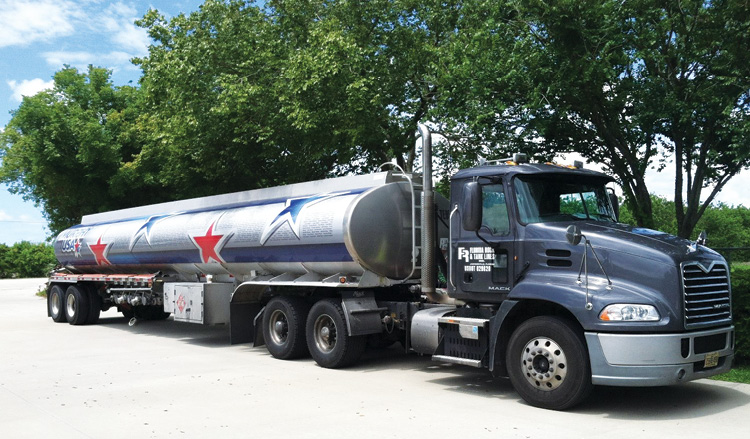
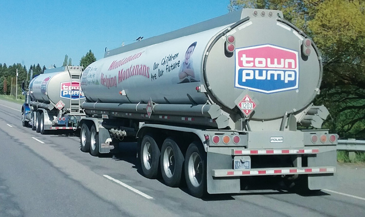
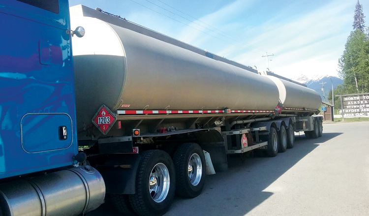
(1) A typical MC-406 tanker trailer and truck tractor. (Photos by author.) (2) A double tanker truck/trailer combination, which is only legal on the highways of some states, such as Montana. (3) This Canadian double trailer combination can transport up to 15,000 U.S. gallons (56,000 liters).
The U.S. Department of Transportation (US DOT) designates the gasoline tanker trailer as MC (motor carrier) 406 (photo 1). Before September 1995, the gasoline tanker trailer was built to slightly different specifications and was designated as MC-306; prior to 1967, the designation was MC-305. The updated MC-406 specifications mandated a thicker tanker shell and better safety performance of the various components during a rollover. Keep in mind that the shell of such a tanker is less than ¼ inch thick. Except for those changes, the MC-306 and MC-406 are very similar. Many MC-306 tankers are still on the road today. Although I have never run across one, there probably are a few MC-305s around.
The general tanker component information here applies in most cases; there are exceptions. For example, although generally gasoline tanker shells are constructed of aluminum, a few tankers were made of steel many years ago. Generally, a ladder will provide access to the top of the tanker; but of the thousands of tankers I have seen, I did see one without a ladder.
Although the US DOT MC-305/306/406 tanker trailers are often called “gasoline tankers,” they haul various products across North American highways. The most common product they transport is gasoline, followed by diesel fuel. A substantial number of these tankers carry a mixed load of gasoline and diesel fuel, since most are multicompartment tankers, commonly with four to five compartments. The typical MC-306/406 tanker carries about 8,000 gallons of product in most states. However, the maximum load that a tanker can carry is designated in pounds, not gallons, and varies state by state. A typical load is 8,000 to 8,500 gallons (approximately 60,000 pounds), depending on what type of product is being transported. In many western states, such as Montana, double trailers are permitted, substantially raising the potential maximum load (photo 2). In some areas of Canada, these capacities can be greatly increased (photo 3).
Tanker Features and Components
Following are a typical tanker’s components/features and what they do:
- The product compartment holds the product being carried.
- The belly valve at the bottom of each compartment allows filling and emptying.
- The emergency shutoff closes all the belly valves at once in an emergency.
- The compartment external valve is on the right side where a flexible hose is attached for off-loading and most times on-loading product.
- The belly pipe (the “wet line”) is the piping under the tanker that extends from the belly valve to the external valve.
- The landing gear are the legs that support the front of the tanker when it is not attached to a tractor.
- The vapor recovery system is a series of pipes and connections to which flexible hose is attached to recover flammable vapors.
- The belly valve controls are mounted in a box and provide individual control to each compartment belly valve.
- The thermistor/optic/Scully outlet is where a device at the loading terminal is plugged into to disperse static electricity and prevent overfilling.
- The pressure relief valves allow pressure to enter or exit the compartment system to keep the pressure within the tank’s design limits.
- The overturn protection/vapor rail is the hollow rail along the top of each side of the tanker that protects the various components on the top of each compartment during a rollover. The right rail is also part of the vapor recovery system.
- The dome hatch is the locking lid for the large opening at the top of each compartment.
- The vapor valve is at the top of each compartment and allows vapor to enter the compartment as liquid product is off-loaded.
- The Scully device is an overfill protection sensing device at the top of each compartment that shuts off the flow of product being on-loaded if an error is made and if the terminal is equipped for same.
- The bulkhead is a solid wall between compartments.
- The baffle is a wall within a compartment with holes in it, designed to reduce the movement of liquid (weight) front to back during transport. The holes are in the middle and at the 6 and 12 o’clock positions. Some have holes at the 3 and 6 o’clock positions and have indicator black dots on the end of the tanker at those positions.
Tanker Tour
Let’s start at the left front of the tanker trailer and go around the tanker in a counterclockwise fashion; then we will go topside.
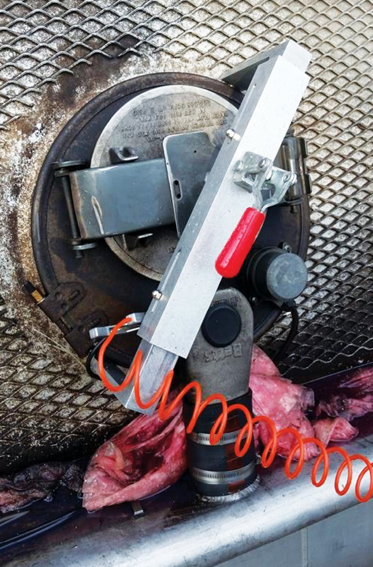
Emergency shutoff. At the left front corner is one of the most important features, the emergency shutoff. This safety device comes in many shapes and sizes and is sometimes marked, sometimes not. It will be on the front or the side of the trailer, very close to the corner. When activated, it is designed to close all the belly valves at once, thus stopping the flow of liquid into the belly piping (wet lines). This would be helpful if a tanker is on its wheels or its side; if the tanker is upside down, it is not an issue. The device is connected to the belly valves by a steel cable (photo 4) or by pneumatic pressure lines (photos 5 and 6). Another safety feature within this system is a high-heat component, either a fusible link in the steel cable or a meltaway line in the pneumatic system that is designed to shut off all belly valves if a fire occurs under the tanker trailer.
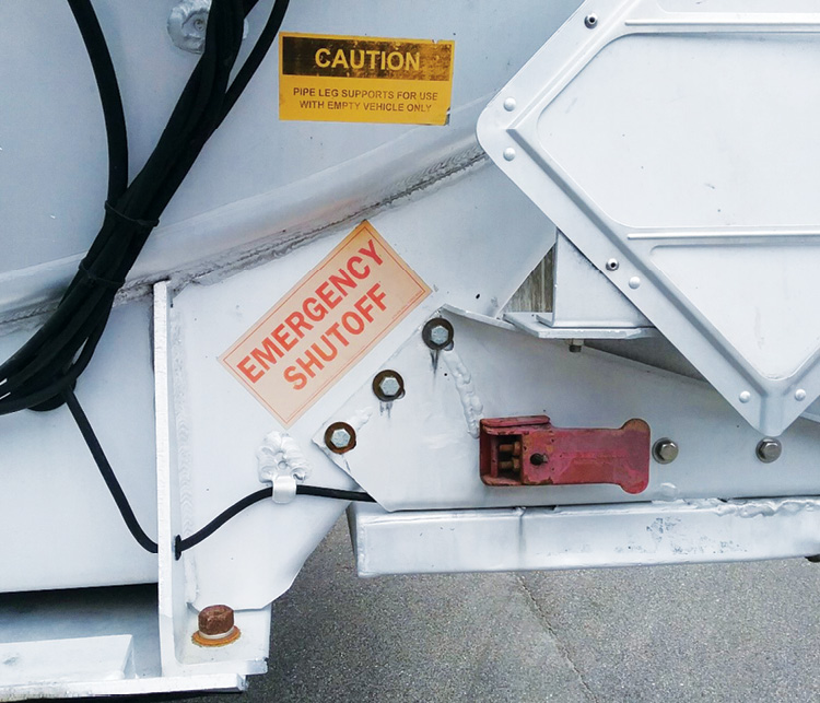
(4) A cable device that is operated by pulling on the red latch.
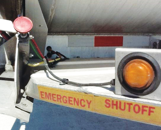
(5) A pneumatic device that is operated by pressing on the round red plunger at the left.
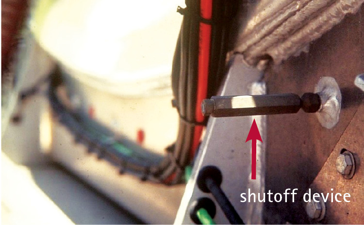
(6) An unmarked pneumatic breakaway emergency shutoff device (arrow) that is operated by the breaking off device.
Specification plate. Moving along the left side, the specification plate is mounted on the side of the trailer, about one-third of the way from the front. Although it is not critical to locate and read the spec plate, it includes such useful information as the MC number (MC 306/406), the material from which the tank is made (AL=aluminum), the total tanker capacity in gallons and pounds, and the maximum capacity of each compartment in gallons (photo 7).
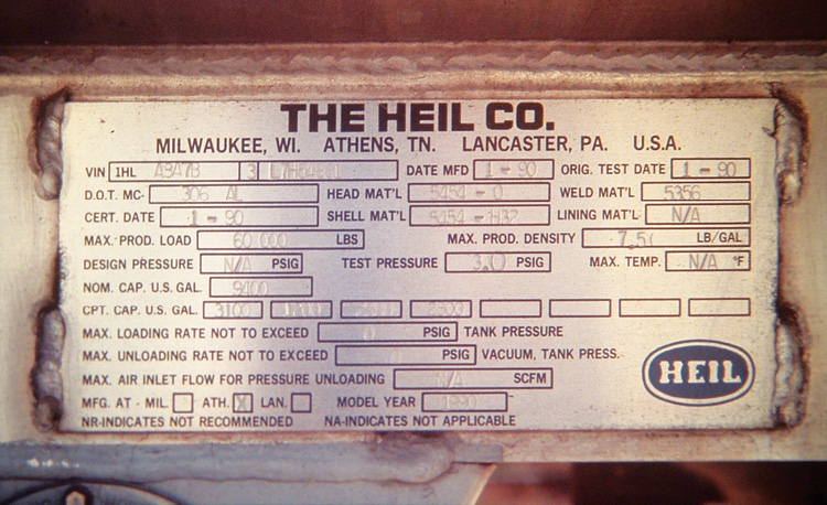
(7) A typical specification plate.
Landing gear. In the same area, under the tanker, is the landing gear. These are two legs, usually made of metal, and a hand crank or pins that allow raising or lowering. You may also find a sticker warning you that they will not support a loaded tanker. However, even if there is a warning label, it may be faded and unreadable as in photo 8 (photos 8 and 9).
Belly pipes. Proceeding to the middle left side, under the tanker are the belly pipes, also known as wet lines. In most situations, unless all the tanker compartments are empty, there will be product in the belly pipes, which are about four inches in diameter and constructed of aluminum. You can figure that each foot of pipe will contain about a half gallon. In the case of an underride by a smaller vehicle, up to 30 gallons of product could be spilled or burning from these pipes. Photo 10 shows the belly pipes of a four-compartment trailer.
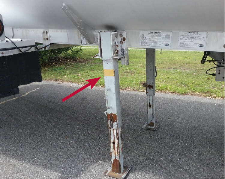
(8) The warning label (arrow) area on this pin-type leg support landing gear is completely faded.
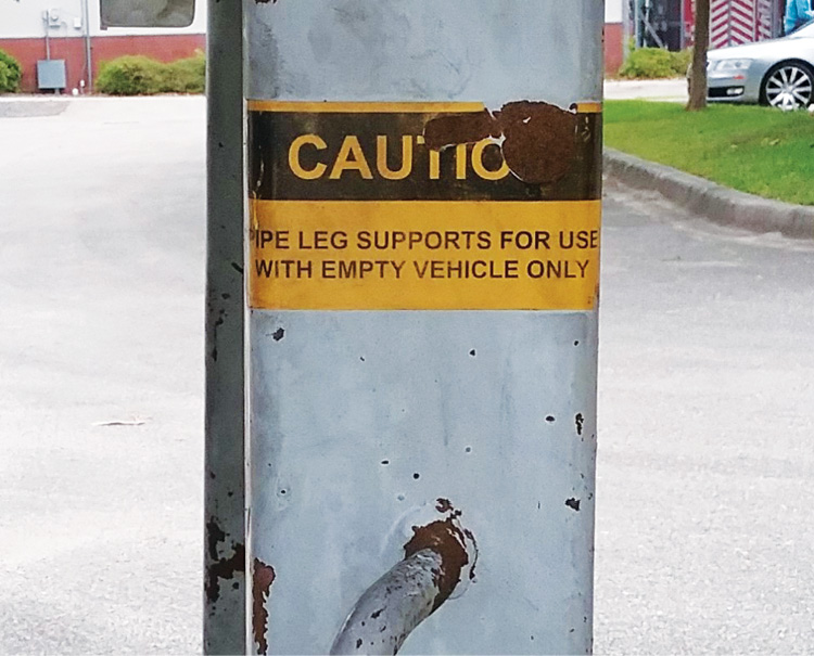
(9) This may be the only warning you will get to prevent a catastrophe. Many legs are not marked.
Double bulkhead opening. Also in this area, looking under the middle belly, you may see a ¾-inch nipple with internal threads; you may see more as you look along the length of the tanker belly. This is a vent hole between bulkheads when two compartments are separated by a double bulkhead, which is common but not always the case. Some transport companies spec the double bulkhead when they order tanker trailers that carry a mixed load, to prevent the costly contamination of two compartments of fuel (one gasoline/one diesel) should a single bulkhead fail or crack. With a double bulkhead, if one cracks, the product will leak from this bottom vent hole but not contaminate either compartment with a fuel mix. Drivers typically carry a plug in their tractor for such events (photo 11).
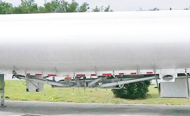
(10) The belly piping (wet lines) of a four-compartment tanker trailer.
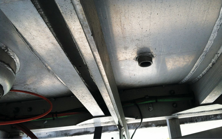
(11) A vent hole between a double bulkhead.
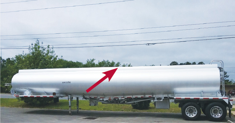
(12) A typical MC-406 tanker trailer. Along the top is the eight-inch overturn protection rail (arrow) through which runs the vapor recovery system and the access ladder at right.
Overturn protection rail. Moving back away from the left middle of the tanker, you can observe the entire tanker, which is pretty much “clean” and devoid of any features on the left side. The overturn protection rail is one good identification feature of the MC 306/406 tanker, an eight-inch-high box on the top running the tanker’s full length, which is not found on other tanker trailer types. The right side overturn protection rail also acts as part of the vapor recovery system. From this vantage point, you may also see a ladder, typically on the rear or possibly on the front of the tanker (photo 12).
Rear of tanker. Moving to the rear of the tanker, observe that the tank is not round; it is more of a flat oval or an elliptical shape, which is specific to the MC 306/406 tanker. No other tankers have this shape. The ladder rails also act as a drain for the eight-inch-deep area atop the tanker that runs its length. If you respond to a “leaking” gasoline tanker parked at a truck stop, the liquid coming from this area is likely snow melt from the top (photo 13).
In some cases, you may observe a secondary emergency shutoff device at the rear of the tanker.
Vapor recovery system. On the right rear, vertical piping for the vapor recovery system may be present. This external piping, if present, will run from one or two connections on the right side of the tanker up to the overturn protection/vapor rail. Some of the newer versions of the MC-406 tanker have this vertical pipe as an integral part of the tanker so it is not visible on the outside; it usually runs through the middle right compartment.
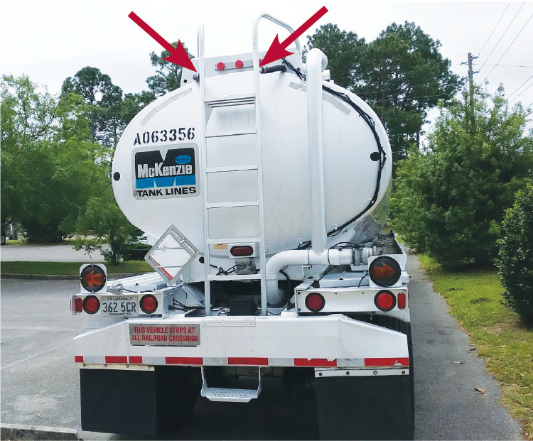
(13) From the rear, note the elliptical shape, the ladder, and the vapor recovery piping. This tanker has baffle holes in the 3 and 6 o’clock positions, as indicated by the black dots. This allows liquid to flow to both sides of the baffle when the tanker is on its side. Also note the water drain hoses (arrows) connected to the hollow ladder rail, as described previously.
Pressure relief valves. Moving to the right side, looking up at the overturn protection/vapor rail, there may be two pressure relief valves on the rail toward the rear. If you cannot see them, they, too, are integral, but they are there (photo 14). One will be a positive-pressure relief and the other a negative pressure relief. The MC-306/406 tanker is a nonpressurized tank; pressures of more than four pounds per square inch will activate the positive-pressure relief so that no more pressure can build up and any negative pressure will open the negative pressure relief valve and allow air to enter so the aluminum tank will not buckle in. A loaded tanker on its right side will leak product from the relief valve.
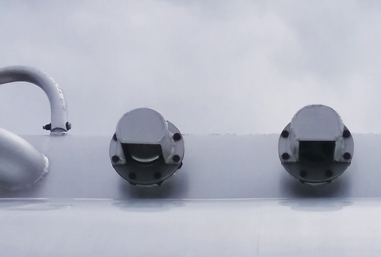
(14) Pressure relief valves.
Compartment external valves. In the middle area of the right side are the compartment external valves and ports (photos 15 and 16). There will be one per compartment. Typically, to the left of the external valve area will be a box with a door to store various fittings and related items. To the right of the external valves will be a box with a door containing the belly valve controls. The driver operator manually operates each external valve individually once the flexible hoses are attached and the corresponding belly valve is opened. The flexible hoses also have built-in grounding wires to dissipate any static electricity during the off-loading. The typical situation is that a compartment of fuel is fully off-loaded at one site. Partial off-loading of a compartment is rare. In many areas of the United States, a loaded tanker is completely off-loaded at one site, whereas a split load is off-loaded at more than one site.
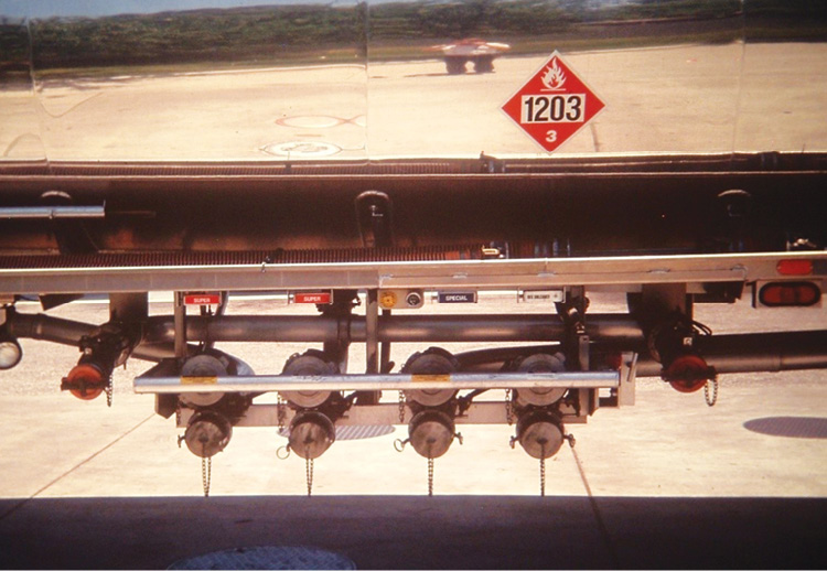
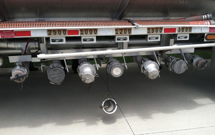
(15) These four external ports and valves have separate intake (top) and discharge ports (bottom). The capped pipes on each side are vapor recovery lines. (16) These five two-way external ports and valves can be used for either intake or discharge, depending on the adapter used. The capped pipes on each side are vapor recovery lines.
In this area you will also find one, two, or three vapor recovery system pipes with capped ends. They are used to recover flammable vapors from the tanks being filled by the tanker as it is being off-loaded. The liquid flowing into the tank being filled pushes the vapors from the tank, which travel through a flexible hose connected from the tank to one of these vapor recovery pipes, thus making it a closed system that does not allow the flammable vapors to escape into the atmosphere. The vapor recovery hose and pipe take the vapors to the vapor recovery rail and back into the tanker trailer compartments.
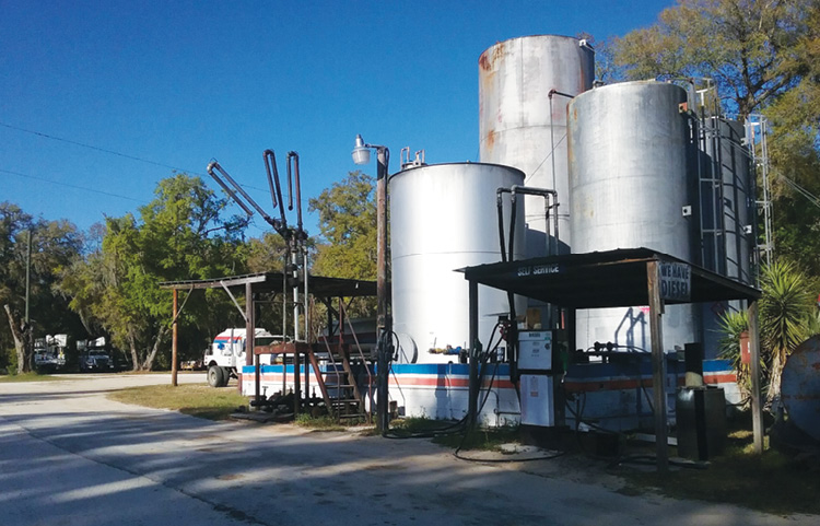
(17) A top-loading fuel dock and tanks.
All tankers are set up to on-load and off-load from the bottom. However, there are still many small loading docks throughout America that may load a tanker from the top (photo 17). Regardless, all tankers off-load from the bottom. The ports on the tanker where the hose is connected at the external valve may be set up in the same way as a fire pumper with separate intake and discharge ports (photo 16). Other tankers may be equipped with a port that can flow both ways, depending on which fitting is attached, as shown in photo 17.
Belly valve controls. They are in a box with a door to the right of the external valves. Most valve box doors are set up with a plunger-type switch that ensures the trailer brakes are activated prior to operating the belly valve. Some of these switches also open all the vapor valves at once when the valve box door is opened. Otherwise, there will be a switch to open all the vapor valves at once before the operator can operate the belly valve. The vapor valves must be opened when product is off-loading to prevent the tank from buckling from negative pressure. The individually operated belly valves are either manually operated (photo 18) by a steel cable from the belly valve to the belly valve controls or by pneumatic air lines (photo 19). Pressure opens the belly valve, and loss of pressure closes it.
Dome hatch/vapor valve. Climbing up the rear or front ladder, we come to the top of the tanker trailer, which looks like a walkway. Each compartment will have a manhole, as seen in photo 20. Within each manhole is the dome hatch, vapor valve, and Scully device.
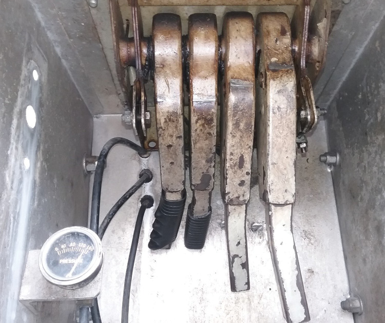
(18) Manual belly valve controls on a four-compartment tanker.
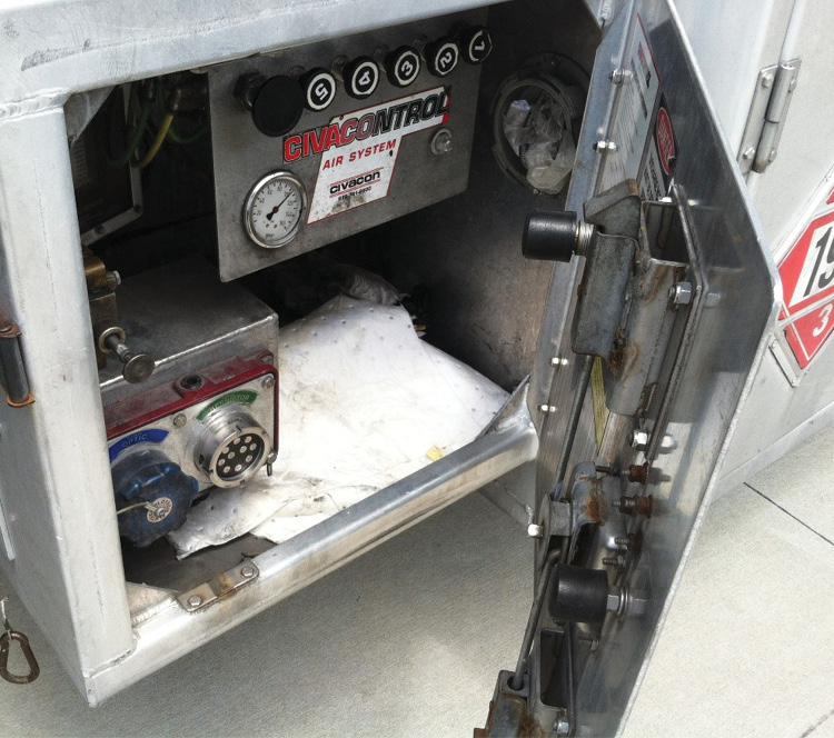
(19) Pneumatic belly valve controls on a five-compartment tanker. Note the two black plungers on the door that release the corresponding actuators when the door is opened. The actuators simultaneously lock the trailer brakes and open the top vapor valves. Also note the thermistor/optic plugs in the lower left for static control at the loading rack.
The dome hatch is the largest opening in a compartment and the most likely to leak in a rollover. Hazmat teams typically are equipped with a dome clamp, which applies pressure to the lid to try to seal it better, since the rubber gaskets on these dome lids are many times brittle and worn (photo 21).
As shown in photo 20, the vapor valve is attached to the right overturn protection/vapor rail by a rubber hose. When opened, the vapor valve prevents the compartment from buckling while product is being off-loaded from the bottom and allows the vapors being pushed out (of a tank being filled) to enter the compartment as part of the vapor recovery system.
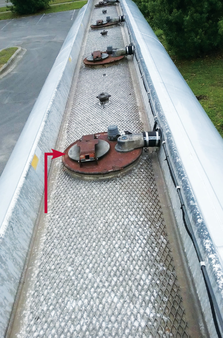
(20) On the manhole, clockwise from left (arrow) are the dome hatch, the Scully device, and the vapor valve.
Product PTO pump. Stepping up to the tractor truck that hauls the trailer, you may see a power take-off (PTO) pump inside the right frame rail of the chassis, between the rear of the truck cab and the rear wheel assembly (photo 22). This pump will pump product to aboveground tanks. Normally, the tanker is off-loaded by gravity feed into a belowgrade tank. However, with an aboveground tank, the product must be pumped. The operator connects a flexible hose from the external valve (of the compartment being off-loaded) to the intake of the pump. A pressure-rated hose is connected between the pump discharge and the inlet of the tank being filled. If the aboveground tank is so equipped, a vapor hose is connected between the aboveground tank vapor outlet and the tanker trailer vapor recovery connection. Grounding connectors may also be employed to control static electricity. The PTO is engaged, and the product is pumped from the tanker compartment to the aboveground tank (photo 17).
(21) A tanker dome clamp.
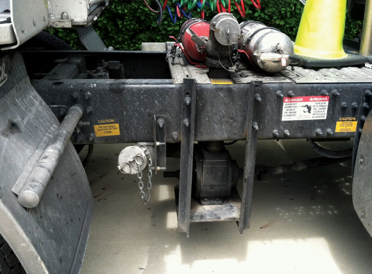
(22) A PTO pump for filling aboveground tanks.
All responders would benefit from seeing and reviewing the features of an MC 306/406 tanker truck. See if your local fuel distributor would bring an MC 306/406 tanker to your department or allow you to visit its facility. If not, check with your local gas station manager and see if you can be present when a tanker is off-loading at the site. You can thus enhance what you learned from this article and better understand the various components and how they work. Speaking with the tanker operator will also provide you with additional information and a chance to have any questions answered.
In Part 2 of this article, I will present various emergency situations that you may face at the scene of a gasoline tanker emergency and discuss some options for safely mitigating them.
LEIGH T. HOLLINS retired as a battalion chief with Cedar Hammock (FL) Fire Rescue after serving 30 years with the department. He joined the fire service with the Nottingham Fire Company in Hamilton Square, New Jersey, in 1976. Hollins is an editorial advisory board member of Fire Engineering and FDIC International and has been a lead instructor for hands-on training at FDIC since 1996.

