By Mike Donahue
During a shoring operation, firefighters have one main goal: to safely transfer the target load from point A to point B. We are of course there to make the structure safe to enter for victim rescue, however if we don’t capture and short the load correctly, we’re jeopardizing not only the victims inside the structure but us the rescuers entering the structure. Like any rescue discipline we perform, “good enough” is not an option here
Let’s examine a few different shoring systems used in these operations, how they work, and the engineering behind the design.
The whole concept behind shoring a load is to transfer the weight from said load from point A to point B, namely the ground. Remember that we are capturing or holding the load in place; we don’t want to move the load because we don’t know the stability of the structure. We also need to remember that every movement has an equal and opposite movement. If I were to lift the slab in figure 1 from point A, I would apply an opposite load force on point B. The problem here is that the load force we’re now applying to point B is being transferred to whatever is underneath it, and whatever is underneath it has loads on the top of it. This creates a domino effect. A good rule of thumb is to think twice and move once. Mentally picture the load moving based on the actions you’re performing. This can save you from making a rather large and possibly fatal mistake if you’re dealing with a trapped victim.
As you read through this article you should pick up on something all these shoring systems have in common.
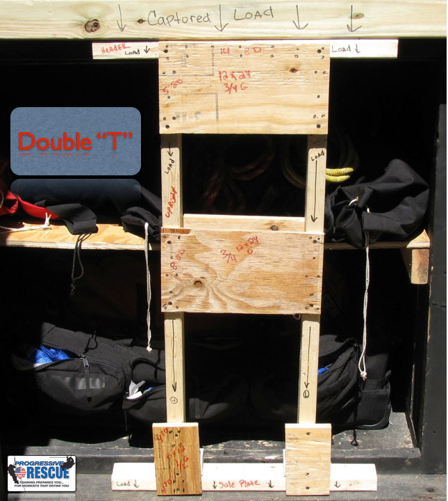
I like to call the double-T shore the big brother of the T Spot shore. It’s superior to the T Spot because it can handle twice the load and it is a permanent shoring system. The T Spot can only be used as a temporary system and would clearly need to be replaced by a permanent system.
The double-T is comprised of four main components: the header, soleplate and two uprights. The header (top portion) collects the load. The uprights transfer the load into the soleplate (bottom). The soleplate transfers the load into the ground, and the job is complete. The components of the system are four gusset plates (two top and two middle). The job of the top gusset plates is to form secure connections between the header and the uprights. The middle gusset plate forms a secure connection between the two uprights. The gusset plates also serve another role; they help to resist lateral forces on the shoring system and help to prevent the system from racking. When driven together, the wedges located between the uprights and sole plate provide and upward force as well as a downward opposite force. This action will secure the shore in place and give it the stability needed to provide a solid path for the load to travel.
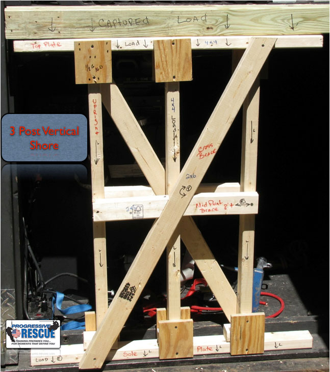
The three-post vertical shore is also referred to as the dead shore. Looking at the shoring system model you should notice the structural components it’s comprised of are the same as the double-T shore. The top plate collects the load. The verticals or uprights provide a path for the load to travel. Finally, the sole plate transfers the load into the ground. Just like the double T, located at the bottom of each upright is a set of 2×4 wedges that, when driven, together create the upward and downward force that provides stability in the system.
Going across the center of the vertical shore is a 2×6 mid-point brace. The job of this brace is to provide the vertical shore with lateral stability. The “x”–created also by 2×6 lumber–is known as a cross brace. The job of the cross brace is to resist any torsional forces applied to the shoring system. All the shoring systems we use are designed to be “earthquake proof,” thus the lateral and cross bracing.
The engineering that goes into the design of these systems is incredible. Everything counts when it comes to the construction, including the amount of nails you use and what type. For instance, when nailing a gusset plate, use 8d nails (plywood to dimensional lumber receives 8d). When nailing dimensional to dimensional such as a 2×6 brace to a 4×4 upright, use 16d. A 12×12 gusset gets an 8 and 5 nail pattern. A half gusset, 6×12, will receive a 4 and 4 nail pattern. Why? Nails have shear strengths and substantial load testing shows these numbers and patterns are what is required to create the shore’s strength.
Now let’s talk about what’s called a raker shore. Don’t get thrown by what it looks like, it’s operating the same way as the double-T and three-post vertical shore. The only differences are the load it’s catching and how it’s doing the job.
The components of the raker are:
- The wall plate
- Sole plate
- Raker
- Cleats
- Wedges
- Thrust block.
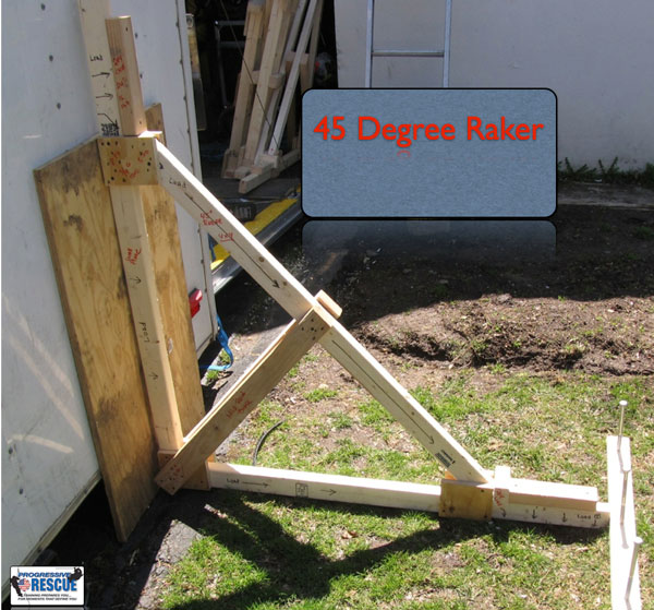
The raker is used to support a wall that is leaning outward. It can be used for other jobs, but let’s focus on supporting of a wall. The first portion of the shore to see the load is the wall plate. Next comes the raker (the angled 4×4). The point at which you want to begin supporting the wall is called the capture point; that’s where the raker would begin on the wall. The 2×4 wedges located between the bottom cleat and where the raker meets the sole plate provide upward force when driven together, snugging the raker and overall system in place. So the captured load now hits the raker and travels down into the sole plate. Once it hits the sole plate, two things happen
1. The load force ravels into the ground and
2. The load force continues to travel through the sole plate and is somewhat terminated once it hits the 24″ 2×4 cleat.
The remaining initial load force hits the thrust block and is forced into the ground. Lastly, you can see two 2×6 midpoint braces. They resist the compressive force the raker is experiencing. They tie the raker to the wall and sole plate, which prevents the compressive load from causing the raker to fail. A great example would be to take a one-foot ruler and press on both sides with the palms of your hands. The compressive force created will cause the ruler to bend.
When we construct shoring systems, we adhere to something called the length and dimension (LD) Formula. We work with two numbers, 25 on the low end and 50 on the high end. Here’s an example of how it works: Take the dimension of the lumber being used (in this example we’ll use a 4×4, the actual dimension of which is 3.5 inches). Take 3.5 and multiply by 50, then take that number and divide by 12 and you will get the max height that lumber can see a load or a force.
Lastly, I like to say the point where the raker hits the sole plate is like the “perfect storm.” You have load force hitting it from the raker, load force traveling through it from the wall plate, and the forces traveling past it striking the cleat and thrust block. There’s a lot going on right there, and this process is constantly going on. The captured load force is continually moving around the raker shore, making a continuous loop. You may think that finding the exact length needed for the raker is difficult but it’s really not. Here’s the math below with examples.
45 Deg Raker. 8-foot Capture Point x 17 = 136-inch length for the raker
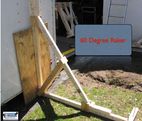
60 Deg Raker. 8-foot Capture Point x 14 = 112-inch length for the raker
The raker shore is doing the same job as the double-T and three-post vertical shore just in a different manner. The important aspects to understand are that method of transfer of the captured load from point A to point B is the same. Like any other shoring system, it needs to be plumb and correctly built to standards. There are no shortcuts here.
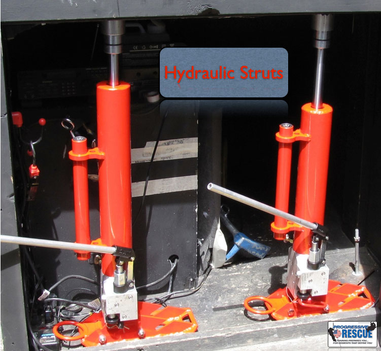
Lastly, let’s look at hydraulic struts, yet another means of creating a shoring system. The nice aspect of these is they can be deployed fast and set up fast, creating a safe haven to construct a wood shoring system. They are also useful if your operation requires a “quick grab,” i.e. the victim is in sight and it’s not going to be a prolonged operation. In the pictured hydraulic shores, the bottom portion is the actual hydraulic unit and a rod stored on the strut is inserted into it and used to operate the strut. The struts themselves can be configured into several different sizes by changing the outer sleeve. Still, the principles of load collection and stabilization are the same. The load is captured at the top of the strut, transferred vertically through the strut then into the ground. With various different bases you can insert headers and sole plates or capture loads by connecting directly to the joists. Consider this another method in your toolbox to complete a shoring mission.
By now you should see that the basic principle of collecting a load is a universal foundation that all shoring systems are based on. Important points to remember when building these systems are:
1. Always ensure the shoring system is plumb. It needs to be plumb to transfer the captured load properly and straight into the ground.
2. Never attempt to ignore the construction standards in place when building these systems. We have them for a reason.
3. Always size-up your operation and determine where and what type of shoring system is needed based on victim location.
4. Remember, for every action there is an equal and opposite reaction. This means what you move is going to apply a load to another part or component of the structure. Take time to visualize what you’re going to do prior to doing it.
Like any other discipline that rescuers perform, training is the key to perfection. We’re in this business to save lives and when lives are at stake, stress levels are extremely high. If your skills are not 100 percent, you become a liability. Read, train and ask questions–these are three important keys to creating and maintaining your knowledge base.
 Mike Donahue has 17 years of fire service experience and has been a career firefighter in the city of Elizabeth, New Jersey, for the last 13 years, working out of Rescue Company 1 for the past 10 years. Mike teaches a Middlesex County College as an adjunct professor and acts as the Fire Service Program Coordinator. Mike is the owner of Progressive Rescue and can be reached at progressiverescue@gmail.com.

