HIGH-RISE FLOWS WITH PRVs: THE BOSTON TESTS
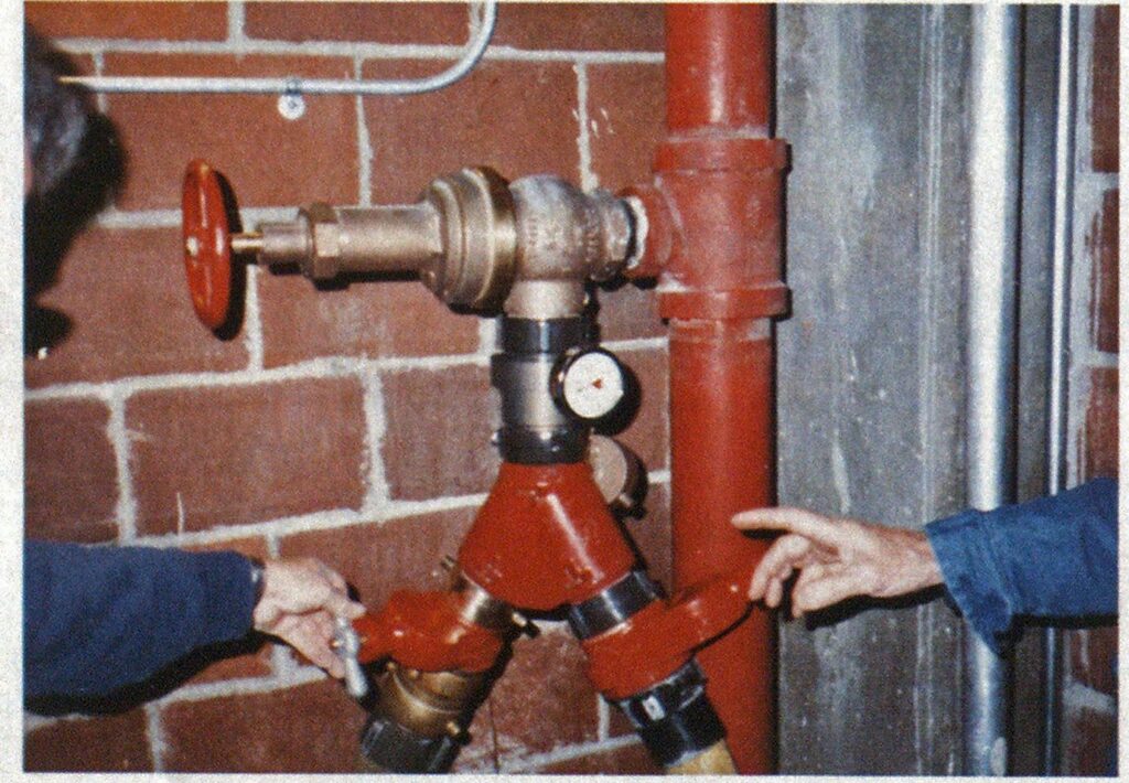
Every building is unique. Even several buildings in a complex designed by the same architect and having the same owner may have similar appearances but not similar fire protection systems. You must visit each building in your jurisdiction to learn about its system before the alarm comes in. Engine Companies 7 and 33 began to set up for the tests early on the designated Saturday morning. A fieldadjustable pressure-regulating hose valve at the basement level of the stair nearest the loading dock was fitted with a piezometer with a 600-psi liquid-filled gauge and a gated 2½by 21/2by 2!/2-inch wye. Two 600-foot lengths of 2‘/2-inch hose were laid from the wye out through the garage to a deck gun on the sidewalk outside the Center with two 2 1/2-inch inlets and a 1 ⅛-inch smooth-bore tip.
Prudential Center in Boston, Massachusetts, includes two major department stores, retail shops, banks, and restaurants in addition to six high-rise buildings. They are Prudential Tower—52 stories plus two basement levels and two penthouses; 101 Huntington Ave. Building—25 stories plus basement and penthouse; Sheraton Boston Hotel—29 stories plus basement and penthouse; and three apartment buildings, each 26 stories with three basement levels and penthouse. The entire complex has 27 acres of underground parking.
Early this year, the Prudential Property’ Company, R.M. Bradley & Co. Inc., Prudential Center property managers, the Boston Fire Department, and Schirmer Engineering Corporation began planning a series of training sessions for the fire department’s responding companies, Prudential security, and the building engineering staff.
The first two sessions included a description of the standpipes, sprinkler systems, fire pumps, and alarm systems in each building and the parking garage. There was a discussion on high-rise standard operating procedures and the interaction of building security and engineering personnel with the fire department during an incident. The group then toured the complex to see the fire protection system’s installation, special features, and components.
A hands-on session on the system was proposed. The Prudential Tow’er fire pump would supply the building’s standpipe system while flowing from one of the lower hose valves. We also would shut off the Tower fire pumps and have fire department pumpers using the Siamese connections duplicate the delivery of the Tower pump. The Prudential Property Company endorsed the hands-on session.
TESTING THE SYSTEM

(Photos by author.)

Next, a hydrant-assist valve was placed on a hydrant supplied by Boston’s high service mains (95 to 100 psi) and a five-inch soft suction line laid to Engine 33. Then a four-inch suction was connected from Engine 33 to Engine 7 for a tandem pumping operation. Two 2‘/2-inch lines from Engine 7 were stretched to the Tower’s standpipe Siamese.
Building fire pumps. The Tower’s electric fire pump was started automatically by opening the hose valve. With both wye gates closed, the piezometer gauge indicated 130 psi, while the pump discharge pressure was 515 psi. Each wye gate slowly was opened to permit the long 2’/2-inch lines to the deck gun to fill. With both gates and the hose valve fully open, the pump discharge pressure was 510 psi and piezometer pressure at the valve outlet was 125 psi with 296 gpm flowing from the deck gun. Both Tower fire pumps and the jocky pump then were shut off. The hose valve and wye gates were closed.
Fire department pumps. Engines 33 and 7, in tandem, raised pressure to 250 psi at Engine 7’s discharge gauge. The hose valve and wye gates were opened as before. With engine pressure held at 250 psi, the valve outlet piezometer indicated 75 psi with a 200-gpm flow.
Engine pressure was increased to 350 psi, which produced 90 psi at the valve outlet while flowing 240 gpm. When engine pressure was increased to 400 psi, outlet pressure was 90 psi with 260 gpm flowing.
This exercise indicates that the fire department pumpers need to produce pressure approaching that produced by the building pumps when PRVs are installed to get usable hose streams if the building pumps are inoperative. This session also raised questions about input pressure vs. output pressure and flows for various types of valves that required addressing.
The Boston Fire Department had a test header built so we could test a variety of hose valves, with pressure in the header provided by pumpers or fixed fire pumps. The six-inch header has a 2 1/2-inch inlet at each end with four 2 1/2-inch outlets on the front side. The horizontally mounted header includes a 1/4-inch outlet at top center for a 600-psi gauge and a small ball valve drain at the bottom center.
VALVE TESTS
Under the command of a chief officer of the Boston Fire Department, Engine 4 took suction from an on-site hydrant at the Boston Fire Academy, and a tandem pumping operation was set up with Engine 39. Two 2’/2-inch lines from Engine 39 supplied the header. The hose valves to be tested were installed one at a time in one of the header outlets, with a 2’/2-inch piezometer on the valve outlet and 150 feet of 2’/2-inch hose to a nozzle. Flows were indicated by a 2’/2-inch venturi and flowmeter in line and pitot tube reading at the nozzle tip. An Underwriters playpipe with 1 ⅛inch tip was used in most flows. A 2 Viinch combination spray nozzle was used for one test. Another test was made with 50 feet of 2’/2-inch hose to the venturi and 100 feet of two-inch to 1 ‘/2-inch combination low-pressure (75 psi) nozzles.


The 2’/2-inch hose valves to be tested were borrowed from several manufacturers. Valves tested were a standard angle valve, a standard angle valve with a pressure-reducer attachment, a restricting valve (limits how far the valve can be opened), and four pressure-regulating valves (PRVs) — two factory set and two field adjustable.
Flow tests were run by pressurizing the header with the hose valve closed, noting header pressure, then opening the hose valve and noting valve outlet pressure and flow. Header pressure was increased and the pressure, valve outlet pressure, and flow were noted. For the pressure range tested, valve outlet pressure and flow increased in direct proportion to the increase in header pressure.
Backflow (flowing into the valve) tests were run by installing two PRVs on the header with both closed. The line from the engine was connected to one valve outlet using a double female swivel, simulating the use of an interior hose valve to pressurize the standpipe when the Siamese is inaccessible or inoperative. The discharge hoseline and piezometer were connected to the other valve outlet. The header was drained and the drain valve was closed. Header pressure was zero psi. Both PRVs then were opened as engine pressure was increased. The valve checked flow and header pressure, and valve outlet pressure and flow remained at zero. With engine pressure approaching 400 psi, no pressure was noted at the header.
CONCLUSIONS
- Pressure loss across a standard 2’/2-inch hose valve is approximately 10 psi with the valve wide open flowing 250 gpm.
- Pressure-restricting attachments and restricting valves act as throttled valves, restricting residual (flowing) pressure and flow. Neither device restricts static pressure or backflow.
- Pressure-regulating valves reduce outlet pressure to some fraction of inlet pressure. These valves must be tested initially after installation to verify proper application and setting while flowing with the building fire pump running. They need to be periodically tested thereafter to demonstrate proper operation equal to the original acceptance test.
- Pressure-regulating valves tested will not allow backflow by pumping into the outlet.
- Standard hose valves, restricting devices, and PRVs are selected and installed based on static and residual pressures available at the connection to the standpipe with the building fire pump operating. To get the pressure and flow expected from the hose valve outlet, fire department pumpers must pressurize the system approximately equal to the level the building
- fire pump would produce.
In buildings where the standpipes supply sprinkler systems, the sprinkler pipe sizes are calculated based on the pressure available at that floor: Higher floors have larger pipe sizes, and lower floors have smaller pipe sizes. Those sizes are based on the building fire pump discharge pressures.
Again, if the building pump fails, the fire department must match the pressure output that the building pump would produce for effective water delivery.
The fire pumps in most high-rise buildings built since 1969 were selected to deliver 250 gpm at 65 psi from the two highest, most remote hose valves. Prior to 1969, the system was designed to provide 250 gpm at 50 psi from the single highest, most remote hose valve. If your standpipe pack contains 150 feet of 1 ½-, 1 ¼-, or two-inch hose with a combination nozzle requiring 100 psi inlet pressure, your engines must provide that extra 60 to 75 psi to produce usable streams. ■

