Energy Fires | By CHRIS G. GREENE and CHRIS PFAFF
Battery electric vehicles (BEVs) have forced an evolution of the modern refueling station. We still pull our car up to a fuel dispensing machine, plug a nozzle-type device into the side of the vehicle, and wait for our tank to fill. However, the difference now is that, with BEVs, a full tank is measured in kilowatts (kW), which directly relates to how far the vehicle can travel. These refueling stations are largely unattended, and we still must pay for our fuel—which comes in the form of electricity rather than flammable/combustible liquids.
Someday, these charging stations will resemble a traditional refueling facility, including a convenience store, hot case, and all other comfort food trappings we have come to enjoy when making that pitstop. However, there is one thing missing from the BEV refueling station that comes with considerable consequences. Currently, the code governing Level 3 charging stations does not require the installation of an emergency shutoff device compliant with National Fire Protection Association (NFPA) 30A, Code for Motor Fuel Dispensing Facilities and Repair Garages. This is a problem, so let’s take a walk through this potential emergency scene.
Response Scenario
You have been dispatched to a refueling station for a reported car fire. While en route, you consider the potential rescue elements, suppression line, hydrant, and so on. In addition, you (and your crew members) are also probably thinking about one more thing: locating and activating the E-Stop (photo 1). For more than two generations of first responders, this has been a fundamental part of our hazard mitigation process for fires at refueling stations. It is unlikely that anyone on your crew is unaware of this device and how it is prioritized in this situation.

(1) A fuel pump E-Stop device used to shut down fuel pumps in emergency situations. Installation of these devices is required by NFPA 30A, and they serve as critical safety features in a fire at a refueling facility. (Photo by Chris G. Greene.)
Now, imagine this same fire incident, only when you arrive there is no E-Stop to be found. The hazard that is most dangerous and difficult to address—uncontrolled fuel release at a refueling facility—cannot be secured in any predictable way. That is exactly what firefighters across the nation had to face prior to 1984, when the first modern E-Stop devices were installed.
To be fair to the industry, automatic overflow shutoffs and fuel hazard mitigation devices and switches were around long before the first E-Stop was installed. The installation of the early fuel control devices was in response to many tragic fires. However, these historic fuel-control safety devices came in the form of breakers and shutoffs located in areas that only a service attendant would understand. Early switches were often manual and were located near the fuel pumps.
You can see the problem with this: Speed and definitive control measures for a fuel leak are imperative. This is one of the gaps that was addressed by the NFPA.
Following are some of the most notable fatal refueling station events:
- In 1906, a fire at a refueling station in New York City killed 11 people.
- In 1910, an explosion at a refueling station in Los Angeles killed 23 people.
- In 1921, a fire at a refueling station in Chicago killed 20 people.
- In 1937, an explosion at a refueling station in Philadelphia killed 23 people.
- In 1949, a fire at a refueling station in Boston killed 11 people.
These tragedies led to calls for safety improvements at fueling stations. In 1950, the NFPA published a standard for emergency shutoff switches. This standard was adopted by many states and eventually by the federal government. In the 1950s, automatic emergency shutoff switches began to be installed. They were activated by a variety of sensors, including heat, pressure, and flame.
In the 1970s, the NFPA began to develop standards for emergency shutoff switches. These standards were updated in the 1990s and again in the 2000s. Today, all refueling stations in the United States are required to have emergency shutoff switches that meet NFPA 30A standards. These standards call for shutoffs to be readily visible and accessible and located at least 20 feet (and not more than 100 feet) from the fueling device location. When a fueling station has multiple pump locations, resulting in the need to install multiple shutoffs, the emergency shutoff devices must be interconnected.
With regard to traditional internal combustion engine (ICE) vehicle refueling stations and Level 3 charging stations, the type of fuel they dispense and their method of delivery are of primary concern and deserve a closer look. There are many control measures and safety features present with both ICE and BEV refueling stations but with stark differences. It is recognized that when we speak of charging/refueling a BEV, there are three types of charging methods, which follow:
- Levels 1 and 2 chargers, both of which use alternative current (AC) voltages of 120 v or 240 v, respectively.
- Level 3 chargers, also known as “direct current fast chargers” (DCFC), which use DC voltages between 400 Vdc and 1,000 Vdc that deliver this energy directly to the vehicle’s battery (Figure 1).
Figure 1. Electric Vehicle Charging Methods: DC/AC
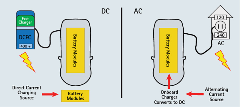
Levels 1 and 2 EV chargers use AC voltages typical to residential sources. Level 3 fast chargers/DCFC use DC voltages between 480 Vdc and 1,000 Vdc. (Figure by Chris G. Greene.)
The DCFC bypasses the vehicles onboard charging system, which, in the case of Levels 1 and 2 chargers, is used to convert the AC energy to DC. This article will focus on the differences and similarities between Level 3 chargers and traditional domestic ICE refueling stations.
Refueling Rate/Speed Capacity: ICE Vehicles and Commercial Trucks
Passenger vehicle fuel pumps in the United States are limited to 10 gallons per minute (gpm) and commercial truck fuel pumps have higher flow rates of 40 gpm. This refueling rate is a national standard; it doesn’t change with different facilities or vehicles. The speed of refueling a traditional ICE vehicle is governed in two ways: pipe diameter and pump speed. It’s a simple control mechanism without a lot of complications, and yet the refueling industry (through the NFPA) saw fit to add emergency stop safety features to assist in an emergency at one of these facilities.
Fueling stations for BEV Level 3 rapid-charging facilities are far more complicated and totally computer dependent. So, let’s look at some of the refueling features for a modern BEV.
The fueling/charging speed for a BEV is influenced by the following factors:
- Rate of charge available at the Level 3 charger.
- Vehicle charge acceptance rate.
- Vehicle charging curve, based on state of charge (SOC).
The rate of charge available relates specifically to the speed capacity of that station and is measured in kWs. The charge available will range from 50 kW to 350 kW. A higher kW rating equates to faster charge/refueling speed. However, BEVs are designed with different energy intake speeds. Simply put, not all vehicles can accept 350 kW of energy. If the vehicle has a 50-kW charge acceptance limit, it will not see the benefits of 350-kW stations (photo 2). The reverse also holds true. If you have a high-performance BEV with a charge acceptance rate of 250 kW and you connect to a 50-kW charger, your higher-performance vehicle will charge much slower than its designed capacity.
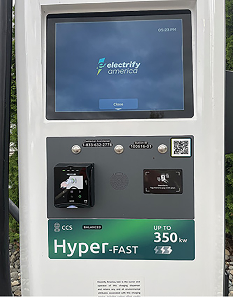
(2) An EV with a lower charge acceptance rate may not benefit from a higher rate of charge station. (Photo by Chris G. Greene.)
The vehicle charge acceptance rate is specific to each vehicle and governs the speed at which said vehicle will allow a charge to be delivered to the battery. This is an internal fuel speed limiter unique to each BEV that, by engineered design, cannot be exceeded by a higher rate of charge. So again, if you have a BEV with charge speed limits of 50 kW, plugging into a 350-kW charging station will not expedite the refueling process more than connecting to a 50-kW station.
The last major influence on BEV refueling speed has to do with a vehicle’s charging curve, which is directly influenced by the vehicle’s SOC when initially connected to the charger. When connected to a charger, the vehicle’s computer is engineered to communicate with the charging station. The speed of charge adjusts based on the vehicle’s state of charge (SOC)—“fuel level of the batteries.”
Refueling will be fastest when the SOC is low and gradually slows as it approaches the 80% SOC threshold. Once the vehicle reports to a charger that is at 80% SOC, the vehicle will not accept a charge at the same rate as it would have at 30% SOC. To clarify, this is a gradual dropoff in speed of charge by design; 80% SOC is often considered a full charge, and packing that last 20% is much more time consuming than the first 80% and may not be good for the health of the battery.
As one can see, there are clear differences between how refueling speeds of ICE and BEVs are controlled. Although the ICE refueling station has one national set standard not influenced by a vehicle or new pump design, the process for fueling a BEV is more complicated and relies on a multitude of computer engineered systems to work correctly. In my opinion, this makes the BEV Level 3 charging system vulnerable to potential failures.
One More Complication
Automakers across the nation have indicated that they will soon be allowed to refuel their BEVs at any of Tesla’s supercharging stations. Non-Tesla BEV owners will need to purchase an adapter to connect their vehicle to the Tesla supercharger. Adapters that allow interchanging of BEVs, including Tesla, at most charging stations have been available for many years. However, these aftermarket adapters have only been applicable to Levels 1 and 2 chargers, where the voltage is AC/240 or less. There is a significant energy difference between a Level 1 or 2 charger and a Level 3 supercharger. This adapter is an additional component to an already complicated refueling control system. Aftermarket charging components that are expected to hold up to 1,000 v DC may be difficult to control from a research and development (R&D) and safety perspective. We will have to wait and see how the industry manages this change.
We do not want to diminish or undermine in any way the diligent efforts of BEV engineers as they work to ensure their product is safe for public use. We recognize that this is part of our future, and the amount of R&D may be unparalleled, but it should not be too much to put a safety feature in place specifically for our first responders. Is the argument, “We have never had a problem at one of our charging stations,” really going to be the barometer that obstructs the installation of emergency stops at these refueling stations? Although the potential for a fire or other emergency incident at a DCFC station, one that involves electrical energy, may be low in frequency, it represents an extreme hazard. The energy hazards at these charging stations are both AC and DC high-voltage electricity; the hazard is invisible and potentially lethal. Absent a clearly marked and readily available shutoff device, in the case of DC energy, 99.9% of our national first responders are unequipped and unprepared to recognize or mitigate this hazard. For guidance on placement of these devices, review NFPA 30A.
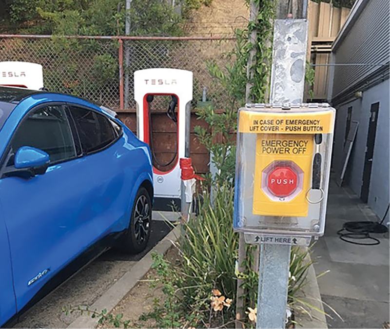
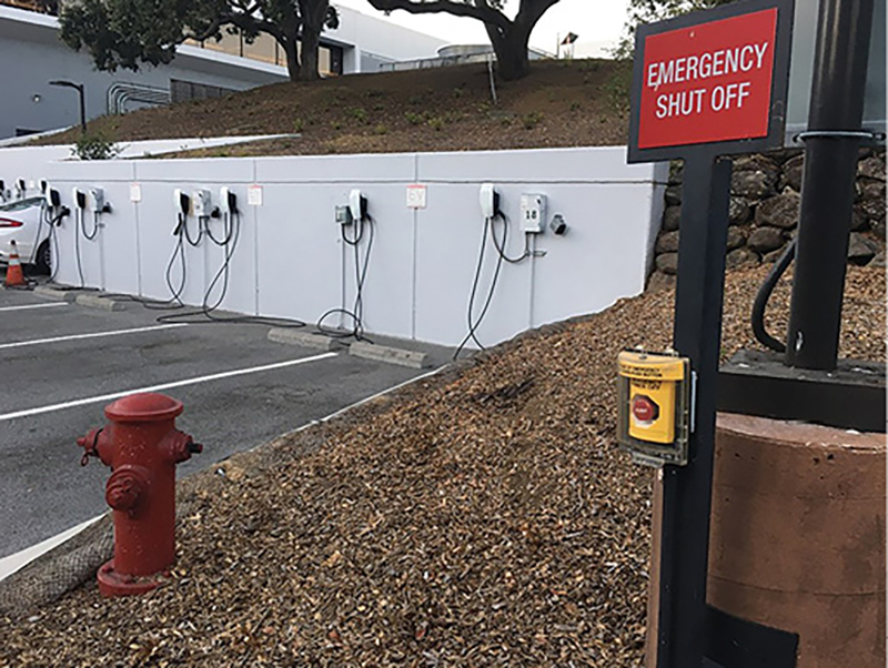
(3, 4) E-Stops installed at a Palo Alto, California, Tesla supercharger station. (Photos by Michael McConnell.)
NFPA 30A: A Quick Glance
When reviewing NFPA 30A, let’s start with the “Origin and Development” section. This portion of an NFPA chapter is often overlooked. However, it is critical to understanding why a particular chapter was created. In the case of NFPA 30A, both the intent and boundaries of influence were made quite clear: “This code originated as Chapter 7 of NFPA 30, Flammable and Combustible Liquids Code, and was developed by the Technical Committee on Flammable and Combustible Liquids to provide more detailed requirements for vehicle fueling and to anticipate the need to address self-service fueling and alternative fuels.”
Electrical energy is the alternative fuel of today’s BEVs, and this is exactly where Level 3 charging stations should have been placed. Unfortunately, and with unanticipated consequences, DCFC/Level 3 charging stations were captured in NFPA 70/NEC 625, National Electrical Code. We can understand why this occurred: BEVs are powered by electricity in the form of batteries, but a wider view scope could and should have placed BEVs into NFPA 30A as an “alternative fuel.” Had this happened, we might not be struggling today to have E-Stops installed at all Level 3 charging stations. Following are several points regarding my immediate concerns:
High-voltage energy hazard (between 400 v and 1,000 v). First responders who must operate at Level 3 charging stations do so in an electrical energy environment that exceeds normal household voltages. First responders are not trained or equipped to operate in such extreme electrical hazard areas absent a shutoff or lock-out device.
Electrical energy hazard is primarily DC. First responders have no tools capable of ensuring that the DC energy hazard has been controlled. Unlike AC hazards, where tools have been made available to first responders that allow them to gather some information about the energy status of electrical equipment, there are very few tools available to first responders for ascertaining DC energy status.
Some E-Stops are being installed in hazardous locations. Although not required at EV charging stations, some vendors are installing E-Stops. Unfortunately, they are being installed at the charging device rather than at safe locations away from the hazard area. Installation of these E-Stops, although well intended, requires that first responders move into the area to operate them. NFPA 30A would require that the E-Stop be located at least 20 feet away from the hazard.
Level 3 EV charging station shutoffs are not clear or easily accessible. NFPA 70/NEC 625 allow shutoffs to be located in locked cabinets that are often not labeled. This creates confusion and frustration for first responders attempting to address the electrical hazards present. First responders will be looking for E-Stop devices similar to what they have seen at refueling stations.
We are at an inflection point with DCFC Level 3 stations. This E-Stop conversation is happening all across the country right now. Keep in mind that the Infrastructure Investment and Jobs Act passed by Congress in November 2021 calls for the installation of 500,000 Level 3 charging stations by 2028. To put this into perspective, today, there are roughly 128,000 traditional refueling stations nationwide, each with NFPA 30A code-compliant emergency shutoffs. Today, as the NFPA 70 chapter is written, none of the 500,000 Level 3 charging stations would be required to install shutoffs as outlined in NFPA 30A.
The strength of NFPA 30A and the safety features it could ensure, specifically for first responders, is absent in NFPA 70. The nexus between ICE and BEV refueling stations is much stronger than that of BEVs and electricity, at least from the general public’s experience. It’s a car; it must be refueled; and, for emergencies that involve a refueling station, first responders expect to have a way to shut off the fuel to be present and operate safely. These devices are not too expensive, and the installation isn’t overly burdensome for this industry.
Unfortunately, as you read this article, we are losing the battle. The original NFPA 30A technical committee showed great vision in how they crafted this chapter. The language used was specific and created for perpetuity to address changes they were forecasting. It is the responsibility of today’s generation of first responders to honor their efforts and ensure that we do not acquiesce when it comes to our safety.
Authors’ note: Special thanks to Robert Largent, environmental engineer with the U.S. Army and Air Force Exchange Service, for his invaluable contributions to this article.
CHRIS G. GREENE is a captain (ret.) with the Seattle (WA) Fire Department and the supervising officer for its Energy Response Team and Program.
CHRIS PFAFF is a captain with West Pierce Fire & Rescue in University Place, Washington. He is also a hazmat technician and hazmat manager/driver for FEMA’s Washington Task Force 1.

