BY BILL GUSTIN
In the fire protection field, few things stay the same for very long. This is particularly true with codes and standards governing high-rise buildings and their fire suppression systems. Fire departments should frequently assess the relevance of their standard operating procedures (SOPs)/guidelines (SOGs) to ensure that they reflect changes in codes and high-rise building systems such as elevators, HVAC, sprinklers, and standpipes. Revisions should also reflect lessons learned from research on wind-driven fires and positive pressurization conducted by the National Institute of Standards and Technology (NIST) as well as lessons learned from high-rise fires examined in fire service publications and on their Web sites. Similarly, procedures should be revised to prevent a repeat of the causes of line-of-duty deaths that have been investigated and reported by the National Institute for Occupational Safety and Health (NIOSH). This article examines the reasons that changes in high-rise building construction and systems and improvements in fire hose may call for revisions of a fire department’s SOPs/SOGs.
PUMP FAILURE “HIGHLY UNLIKELY” BUT POSSIBLE
When firefighters conduct a prefire plan of a high-rise building, the building’s engineer often assures them that they won’t ever have to worry about fighting a serious fire in the building because the building is fully protected by sprinklers and equipped with powerful fire pumps to boost pressure to upper floors. Several building engineers have told me that it is not necessary for the fire department to pump into a building’s fire department connections (FDCs) to pressurize sprinkler and standpipe systems because the chance of the building’s fire pumps failing is “highly unlikely.” At a flow test of a newly constructed 55-story building, the fire suppression system contractor cautioned firefighters not to pump more than 350 pounds per square inch (psi) into the building’s standpipe system because that was the highest pressure permitted by National Fire Protection Association (NFPA) 14, Standard for the Installation of Standpipe and Hose Systems. Additionally, he advised against pressurizing an FDC above 175 psi, the rated pressure of most FDCs. This contractor was right about the pressure limitations of standpipe risers; however, piping from FDCs to risers must also be rated at 350 psi. An engine company supplying an FDC must perform the same function as the building’s fire pumps. The only alternative to an FDC that can supply the upper floors of a very tall high-rise building is a secondary water supply consisting of a pump and water tanks located near the top of a building.
Standpipe systems in many high-rise buildings are divided into zones to keep pressures from exceeding 350 psi and still have the capability of supplying water to upper floors (photo 1). For example, a 50-story building may have a low zone ranging from the first floor to the 25th floor. A fire pump on the first floor supplies floors 1 to 25; a fire pump on the 25th floor supplies water from the 26th floor to the roof. Building engineers who believe that fire pump failure is highly unlikely are right. Fire pumps in modern high-rise buildings are extremely reliable when they are properly inspected, tested, and maintained, but fire pumps have failed and will fail.
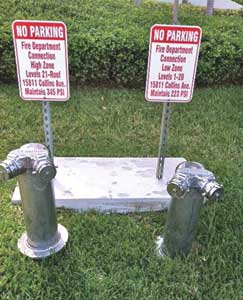 |
| (1) This high-rise building’s standpipe system is divided into two zones to keep pressures from exceeding 350 pounds per square inch (psi). (Photos by Eric Goodman unless otherwise noted.) |
So what could cause a building’s fire pump to fail and require firefighters to rely on their fire apparatus pumps to pressurize a fire suppression system? First, consider that if a fire pump is driven by a diesel engine that it may fail to start because of a dead battery or some other mechanical problem. Fire pumps driven by electric motors can fail to start if their controllers are not set in the “automatic” mode or if there is a failure of the pump’s automatic transfer switch that directs power to the pump from the building’s emergency generator in a power failure.
Consider also a fire involving a cable raceway or a bus duct that delivers electrical power to fire pumps on an upper floor. Of particular concern in coastal areas is the strong possibility of a hurricane’s storm surge flooding lower-floor mechanical rooms and wiping out electrical vaults, switch gear, and emergency generators. Never rely entirely on a building’s fire pumps to supply water for firefighting. You must be ready to take over their function with fire apparatus pumps at any moment by pressurizing a building’s FDCs. It is disturbing, however, that standpipe systems may not withstand the pressure that fire departments may have to pump into them. Following is a review of procedures for pressurizing FDCs.
SUPPLYING FDCs
First-arriving engine companies on a high-rise assignment should immediately locate a building’s FDC and the closest fire hydrant, keeping in mind that connecting to the closest hydrant to an FDC may place apparatus and their operators in the range of falling glass. Preparations for supplying an FDC should be made on alarm system activations, however frequent, as well as telephone reports of a fire. It is very important to understand that there may be a serious fire in a high-rise building without any indication from its exterior. Additionally, at the first indication of a working fire, it is a good idea to a have a second engine connect to a second FDC and secure a second source of water. Most modern high-rise buildings have combination sprinkler and standpipe systems. Sprinkler piping at each floor is connected to standpipes, and the flow to sprinklers is controlled by a floor valve (photo 2). Buildings with large floor areas may have looped systems connected to two or more standpipes and two or more floor valves per floor. Older buildings may have separate sprinkler and standpipe systems. Each system will have its own FDCs that are required to be labeled and, in some jurisdictions, color-coded-for example, red for standpipes and green for sprinklers (photo 3).
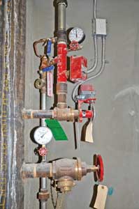 |
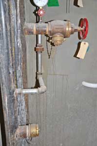
| (2) A combination standpipe/sprinkler system. A pressure-reducing sprinkler floor control valve is tapped into the standpipe riser above a pressure-reducing 2½-inch hose outlet. Note the supervisory switch on the floor valve’s hand wheel, the water flow switch, and the system side pressure gauge. The pressure-reducing floor valve keeps pressure in the sprinkler piping and heads from exceeding 165 psi. To further safeguard the system, a relief valve, located opposite the system pressure gauge, is set to open at 175 psi and dump water into drain piping, seen to the right of the riser. |
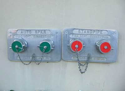 |
| (3) This old high-rise building has separate sprinkler and standpipe systems. The plugs for the sprinkler system fire department connection (FDC) are green; the plugs for the standpipe FDC are red. |
Using separate FDCs for sprinkler and standpipe systems has brought about one of the great debates in the fire service: Which FDC should be supplied first? Fire officers who advocate charging the standpipe FDC first have a valid argument that supplying water to firefighters operating hoselines is paramount. They want to know if there is a closed valve or a burst pipe before firefighters reach the fire floor. Additionally, they may have had a bad experience fighting fires in partially sprinklered buildings where flowing sprinklers had no effect on a fire but made smoke conditions worse. Fire officers who advocate charging the sprinkler system first will argue that the sprinklers are already on the scene of the fire and are, hopefully, keeping the fire in control until it can be extinguished by firefighters with hoselines. Pressurizing the sprinkler system FDC gives sprinklers their best shot at controlling a fire. Advocates for charging sprinklers first will further argue that it may take several minutes for firefighters to reach the fire floor and operate hoselines; therefore, there will be plenty of time to connect and pressurize a standpipe FDC.
A similar argument can be made for and against sending the entire crew of the first-arriving engine company into a high-rise building. This is a common procedure for fire departments with three-person engine companies. Those in favor of this procedure will argue that leaving the driver-engineer with the apparatus leaves only two firefighters to begin an investigation. Some departments’ high-rise procedures designate the driver-engineer of the first-arriving engine as an elevator-control firefighter. Opponents of deploying the driver-engineer with the crew will argue that it takes the individual who is most familiar with the location of hydrants, FDCs, and operating pressures away from the apparatus. The location of FDCs is best determined during prefire planning and verified by periodic visits by fire companies.
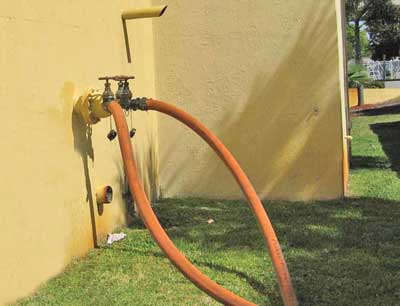
According to NFPA 14, an FDC must have signs that indicate what it supplies, such as sprinklers or standpipes, as well as the required pressure. Locating an FDC can be difficult when it is hidden in shrubbery or behind parked vehicles. Fire departments should determine if the building code in their area requires a maximum distance between an FDC and the closest fire hydrant, such as 100 to 150 feet. NFPA 14 allows a maximum of 100 feet. If this is the case, a hydrant close to a building may be some indication of the location of an FDC. Some jurisdictions require or permit FDCs with a single large-diameter Storz inlet. FDCs with connections for large-diameter hose are fine as long as the required inlet pressures do not exceed the pressure limitations of a fire department’s large-diameter hose. This is a critical consideration when a fire department uses large-diameter supply hose with a maximum operating pressure of 185 psi.
Remove the plastic or metal protective caps from the FDC’s female swivel connections by striking them with a tool. When an FDC has male threaded plugs, remove at least two of them before the FDC is pressurized. This is very important because it is a common practice to initially pressurize the FDC with one 2½-inch or three-inch hoseline and then connect and pressurize a second hoseline. FDCs are equipped with clappers that prevent water from flowing out of intakes; however, a clapper may fail to completely seal off an intake and allow dangerously high pressure to build between the clapper and a threaded male plug. A male plug that is under pressure can become a dangerous missile when it is unscrewed from an FDC. Use extreme caution anytime a threaded cap or plug is difficult to unscrew because it is probably under pressure. You may still encounter very old two-inlet FDCs that have a clapper that swings only to the right to seal off the right inlet. In this case, pressurize the left inlet first. Before connecting hoselines to an FDC, check the FDC for debris. FDCs with missing caps are magnets for trash. Use a tool such as a spanner wrench, not your hands, to remove debris. Use the tool to push open clappers to check for debris and insect nests (photo 4).
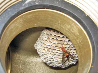 |
| (4) Wasps have taken up residence in the FDC that is missing its protective cap. Use a tool, not your hand, to push open clappers and remove debris. |
Driver-engineers supplying an FDC should expect the female swivel connections to be frozen and be prepared to improvise with double male and female adaptors. They should also expect to find gaskets missing in the female connections and be prepared to install them from the supply of spare gaskets carried on the apparatus. It is common to find high-rise buildings with zoned standpipe systems; each zone will have its own FDCs. There are times when companies attempting to locate a fire cannot rapidly determine from which standpipe zone they will operate. In this case, initially pressurize both the high zone and low zone by connecting one 2½-inch or three-inch hoseline to each zone’s FDC.
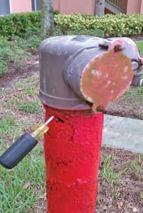
In recent years, urban fire departments have experienced a rash of thefts of plugs and swivels from FDCs, which are sold for scrap metal. In some cases, entire FDCs have been stolen by wrapping them with a chain and using a vehicle to pull them out of the ground or off a building. FDCs are also prone to failure, as shown in photos 5 and 6. When engine companies encounter a missing or damaged FDC, they should attempt to locate and supply another FDC. If supplying another FDC is not possible, pressurize standpipes by connecting 2½-inch or three-inch hoselines to lower-floor hose outlets. Buildings equipped with pressure-reducing valves (PRVs) cannot be supplied through standpipe outlets because they act as a check valve. PRVs are discussed later in this article.
 |
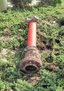 |
| (5-6) These FDCs have failed, necessitating supplying the standpipe system from a first-floor outlet or, in the case of PRVs, the fire pump test header. In photo 5, salt air has corroded the pipe below the FDC to a point that it can be penetrated with a screwdriver. In photo 6, this FDC was “launched” when pressurized to 125 psi. (Photos by Mac McGarry.) |
HIGH-PRESSURE PUMPING
When pumping FDCs at pressures necessary to fight a fire on the upper floor of a high-rise building, you must realize that the basic principles of hydraulics are definitely not on your side. Remember that it takes 4.34 psi to raise a column of water 10 feet. For practical application, round 4.34 psi to five psi and consider that each floor above the first floor is 10 feet in elevation. Now, consider that the roof of a 50-story building is, in terms of elevation, the 51st floor-that’s 50 stories above the ground floor. Multiply 50 floors by 5 psi per floor, and you can see that it would take at least 250 psi just to get water to the roof. That’s not considering friction loss in the system, hoselines, or nozzle pressures.
This quick and dirty calculation is far from exact because it doesn’t take into consideration that floors in many high-rise buildings average 12 feet in height and that the first floor may be the equivalent of three upper floors because of lobbies, mezzanines, mechanical rooms, and loading docks. As a result, it is not uncommon to find a 50-story building that is close to 600 feet in height. To determine if hoselines connected to standpipe outlets are receiving adequate pressure, use an in-line gauge and read the pressure when the nozzle is fully opened and flowing. Do not, however, rely entirely on reading an in-line gauge to determine the proper pressure; it could be inaccurate. There is no substitute for the judgment of an experienced firefighter who assesses the quality of a stream by its reach and nozzle reaction. If a stream is judged to be weak, increase the pressure by opening the outlet valve. If the outlet is opened completely, radio the pump operator supplying the FDC to raise the proper pump discharge pressure (PDP). It is very important that a stream’s pressure and quality be determined before you enter a hostile environment. Flow the nozzle on the floor below the fire or in a tenable enclosed stairwell.
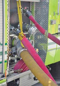
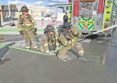
Pumping FDCs at high pressures can result in a burst hoseline that can result in a serious injury. To prevent injuries, connect hoselines to discharges on the right side of apparatus, not at the pump panel. Lash hoselines to apparatus and FDC with rope or nylon webbing (photos 7-8), and use scene barrier tape to isolate the area near the apparatus, hoselines, and FDC. Additionally, some fire departments specify special high-pressure hose specifically for pumping FDCs. Conventional fire hose manufactured in the past few years has made pumping at high pressures safer because it can withstand substantially higher pressures than older hose. For example, Miami-Dade (FL) Fire Rescue is gradually replacing older 2½- and three-inch hose with new hose that has a service test pressure of 500 psi. Additionally, improvements in large-diameter hose have resulted in higher operating pressures, which can be very important for fire departments that supply FDCs with large-diameter hose inlets.
 |
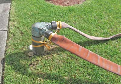 |
| (7-8) To prevent injury if a hoseline bursts during high-pressure pumping, connect hoselines to discharges on the right side of the apparatus, not at the pump panel. As an added precaution, lash hoselines to the apparatus and FDC with nylon webbing. |
A few years ago, Miami-Dade (FL) Fire Rescue had the opportunity to conduct flow tests in a newly constructed 55-story, 600-foot-high residential building on the Atlantic Ocean. The building has two electric fire pumps on a lower floor, which supply a combination sprinkler/standpipe system consisting of two zones. One pump supplies the low zone, from floors 1 to 25. Both pumps supply the high zone, from floor 26 to the roof. The pumps operate in series to supply the high zone; the low-zone pump discharges into the high-zone pump’s intake, which essentially doubles the pressure developed by the low-zone pump. There is no fire pump on an upper floor; hence, there are two standpipes, a high zone and a low zone in the stairwells from the first floor to the 25th floor. The high-zone standpipe can withstand higher pressures than those for the low zone and has no hose outlets from floors 1-25. After testing the building’s fire pumps, fire officers asked the building’s sprinkler contractor to shut them down to test the fire department’s ability to supply the standpipe system through an FDC. The contractor reluctantly agreed and warned the fire officers of the possibility of bursting a pipe. Because the contractor would be financially responsible for any water damage, he positioned workers throughout the building to check for leaks or a burst pipe.
A 1,500-gallon-per-minute (gpm) engine pumped two 2½-inch hoselines to a high zone FDC; 2 1⁄2-inch hose was used because it had the highest service test pressure of hose in use at the time. Two 2½-inch hoselines connected to roof standpipe outlets flowed more than 500 gpm. This necessitated the engine’s supplying the FDC to pump at a pressure of more than 400 psi. This pressure is impressive considering that the apparatus had a single-stage pump. The apparatus used in this flow test was almost brand new. Using a new apparatus was, in hindsight, a big mistake because it is highly unlikely that its performance is representative of the entire fleet. In retrospect, we should have used a tired old spare rig to have more realistic expectations of how our apparatus will perform at pumping high pressures. Miami-Dade’s fleet of apparatus is equipped with single-stage, 1,500-gpm pumps. Single-stage pumps are not ideally suited for pumping high pressures; consequently, the apparatus engine operated close to its maximum governed revolutions per minute (rpm).
Apparatus with two-stage pumps can develop higher pressures at lower engine rpm than single-stage pumpers when they are operated in series-when one stage’s impeller discharges into the second stage. There, the second-stage impeller raises the pressure developed by the pump’s first stage. Some fire departments have specialized high-pressure engines specifically for supplying FDCs of extremely tall high-rise buildings. The Fire Department of New York, for example, has engines in high-rise districts that are equipped with three-stage pumps and specialized hose for supplying FDCs at extremely high pressures. Similarly, the Chicago (IL) Fire Department has engines with a separate booster pump that can be engaged for high-pressure pumping.
Supplying standpipes with single-stage pumps may require a tandem pumping operation involving two pumpers to develop the required pressure. One engine connected to a hydrant pumps into the intake of the engine pumping the FDC, which raises the pressure developed by the first engine (photos 9-10). There are various methods for performing tandem pumping, which is essentially a very short relay because the engines are no farther than 100 feet apart. Let’s examine one method that uses a four-way hydrant valve and large-diameter supply hose-that’s right, large-diameter supply hose with a maximum operating pressure of 185 psi. A four-way valve allows a second pumping apparatus to raise pressure in a supply line laid from hydrant to fire without interrupting the flow of water. This is necessary when hydrant pressure alone is insufficient to overcome the friction loss in the supply hoseline. The four-way valve can, in a similar fashion, facilitate the connection of a second engine to boost the intake pressure of an engine pumping an FDC.
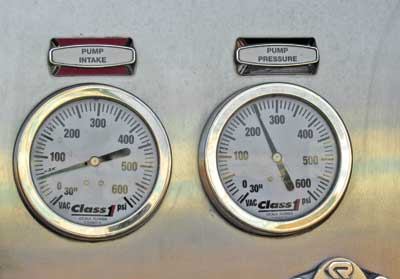 |
| (9) An engine pumping 600 gpm at 250 psi receives 50 psi residual pressure from a hydrant. The engine’s pump is developing a net pump pressure of 200 psi. (Photos by Mac McGarry.) |
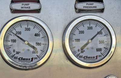 |
| (10) An engine tandem pumping 600 gpm at 400 psi receives 170 psi from a second engine connected to a hydrant. The engine’s pump is developing a net pump pressure of 230 psi. |
If an apparatus pumping an FDC is not capable of developing the required pressure, a second apparatus will connect to the four-way valve at the hydrant and pressurize the supply line to the engine pumping the FDC to a maximum pressure of 185 psi, the maximum allowable pressure for large-diameter supply hose. Raising the intake pressure of the engine pumping the FDC substantially reduces the total pressure its pump will have to develop to reach the pump’s PDP. For example, if the fire pumps in a 70-story building were to fail, the fire department may have to pump as much as 500 psi or higher to an FDC. Say the apparatus pumping the FDC receives 150 psi, as read on its master intake gauge. In this case, it will have to develop an additional net pump pressure of 350 psi to reach the required pump discharge pressure psi.
There are factors that limit the pressure that can be produced by this operation. First, the LDH connected between pumpers is limited to a maximum operating pressure of 185 psi. Using conventional 2½-inch or, preferably, three-inch hose between pumpers will allow for higher pressures. Second, intake relief valves on the apparatus pumping the FDC will open and dump water if they receive water at a pressure over the relief valve’s setting (photo 11). The best way to prevent this from happening is to specify apparatus with a pilot-operated intake relief valve that can be easily adjusted at the pump panel to as high as 250 psi. Intake relief valves that cannot be adjusted at the pump panel can be adjusted using a wrench to tighten a spring, increasing the valve’s ability to hold back pressure without opening. This is a procedure that is better performed at the repair shop than on the fireground because it involves working under an apparatus. The dump pipes on intake relief valves have 2½-inch hose threads to connect a hoseline to direct the valve’s discharge away from underneath the apparatus. It may be tempting to simply cap off these threads to circumvent the intake relief valve. Don’t do it! Pumping at high pressures without a relief device on the intake side of a pump is a recipe for pump damage, burst hoselines, and bodily injury.
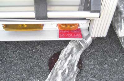 |
| (11) The pump’s intake relief valve opens and dumps water. Note the red warning sign that the dump pipe not be capped. |
Another device that can limit the pressure that can be developed by a pump is an electronic pressure control governor. Electronic governors have two operating modes: pressure and throttle or rpm. When some electronic governors are operated in the pressure mode, they limit PDP to a set value, such as 300 psi. In this case, operating the governor in the throttle/rpm mode will allow the pump to develop higher pressures. Issues concerning high-pressure pumping, such a relief valve settings and maximum allowable pressures, should be addressed with input from fire hose and apparatus manufacturers, shop superintendents, and training officers. Additionally, it is crucial to consult with fire prevention or building department personnel who are familiar with the pressure limitations of fire suppression systems in the fire department’s jurisdiction. Address issues concerning high-pressure pumping operations in a conference room and on the drill ground, not on the fireground.
It is important to understand that a building’s fire pumps and fire apparatus pumping FDCs cannot supply a fire suppression system at the same time; it is either one or the other, depending on which one is developing the highest pressure. Pressure in the municipal water system and developed by a building’s fire pumps is exerted on a clapper valve in the piping connecting the FDCs to the discharge side of the fire pump. A fire department pumper supplying an FDC must exceed the pressure in the system to open the clapper valve. If a fire department pumper does not exceed system pressure, it will flow no water because it is pumping against a closed clapper valve. Pumping at high pressures with little or no water flowing will rapidly cause an apparatus pump to overheat and self-destruct. Apparatus pumping at high pressures must continuously flow at least 100 gpm to prevent the pump from overheating. This can be accomplished by connecting a hose without a nozzle to a discharge, lashing it to a stationary object (a storm sewer grating is ideal), and partially opening the discharge (photo 12). Pump operators must constantly check their pump for overheating by feeling the pump’s steamer connection; if it is getting hot to the touch, the pump is not flowing enough water.
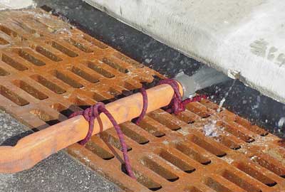 |
| (12) A hose lashed to a storm sewer grating flows water to keep the pump cool. |
How does a pump operator pressurizing an FDC determine if the apparatus pump is flowing water into a building’s fire suppression system or pumping against a closed valve? Slowly close the discharge valves to the hoselines connected to the FDC. If the apparatus pump is flowing water into the system, the pressure on the individual discharge gauges will drop as the discharges are closed. Additionally, the residual pressure, as read on the pump’s compound (intake) gauge will rise because less water is flowing from the pump. If all pressures remain the same as discharge valves are closed, the pump is not flowing water or is flowing such a negligible amount of water-from a sprinkler head, for example-that the differences in pressure will not be detectable.
This begs the question: When a building’s fire pumps are operating and developing sufficient pressure, why operate a fire department pumper at a high pressure? There are pros and cons to this practice.
Pros: Say an engine connects to an FDC and pumps at idle or doesn’t even engage the pump. If a building’s fire pump fails and firefighters lose water, there will be a delay in restoring pressure because the pump operator must be notified to raise his PDP. Consequently, firefighters on a limp hoseline may be seriously burned.
Cons: First, pumping an FDC at a high pressure may burst a pipe, rendering a riser or the entire sprinkler/standpipe system inoperable, causing water damage. Second, pumping at high pressures puts unnecessary wear on apparatus.
PRV BASICS
One of the most significant changes in a fire department’s high-rise procedures may be the section on PRVs. The reason for this is that almost all high-rise buildings constructed in the past several years are equipped with pressure-reducing standpipe outlet valves and sprinkler system floor zone control valves. PRVs limit static pressure when no water is flowing and when there is pressure downstream of the valve when water is flowing. This distinguishes them from pressure-restricting devices (PRDs) that reduce pressure only when water is flowing; PRDs have no effect on static pressure. They function by limiting how far a standpipe outlet can be opened or by restricting the size of the discharge outlet. Some PRDs can be disabled by pulling a pin, removing it using an Allen wrench, or disconnecting it from a valve’s discharge threads.
NFPA 14 requires that standpipes installed after 1993 must deliver a minimum residual pressure of 100 psi at every standpipe outlet from the ground floor to the roof. Additionally, NFPA standards require that standpipe outlet pressures do not exceed a static and flow pressure of 175 psi. These requirements can create a problem. Consider a 25-story building with a fire pump on the ground floor. Remember that it requires 4.34 psi to push a column of water 10 feet. Again, for simplification on the fireground, we round 4.34 to five psi and 10 feet for every floor above the ground floor. Now to simply get that column of water to the roof of the 25-story building (that’s the equivalent of the 26th floor, hence 25 stories above the ground floor), it will require 125 psi (25 floors × 5 psi + 125 psi).
Although 125 psi is the absolute minimum pressure necessary to overcome elevation to the roof, remember that NFPA 14 requires a minimum pressure of 100 psi at every standpipe outlet. To achieve this, there has to be a pressure at the base of the standpipe of 225 psi-that’s 125 psi for elevation plus 100 psi for the minimum required outlet pressure. In reality, the pressure could be significantly higher to overcome friction loss in the system. This is explained later.
Now, let’s say a fire occurs on the fifth floor and firefighters stretch a hoseline from a fourth-floor standpipe outlet. The building’s fire pump doesn’t know what floor the fire is on and cannot adjust its pressure accordingly. The fire pump develops only one pressure, the pressure necessary to flow a combined flow of 500 gpm at 100 psi from the two most hydraulically remote outlets on a riser.
The pump must also be capable of supplying the uppermost outlets of additional risers at 250 gpm at 100 psi for buildings with floor areas that do not exceed 80,000 square feet.
Additionally, the pump must be designed to overcome the friction loss in the system at these pressure and flow requirements. Accounting for elevation loss (5 psi per floor × 3 floors above the ground), the pressure at the fourth-floor standpipe outlet would be at least 210 psi (225 psi − 15 psi elevation loss). Again, that’s not factoring in friction loss in the system. The fourth-floor outlet pressure exceeds the maximum standpipe pressure allowable by the NFPA, 175 psi-hence, the reason for PRVs.
PRVs reduce pressure by means of a valve that floats or “throttles” in a range from a fully open to a closed position in response to pressure downstream of the valve. One of the most significant identifying features of a PRV is that there are no threads in the valve’s floating stem. This can be seen when looking into the valve outlet (photo 13). Most PRVs can also be identified by the large rim of their upper bonnet. This, however, isn’t always the case. For example, the PRV in photo 14 has a rim not much larger than a conventional valve.
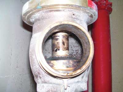 |
| (13) A look inside a hose outlet: Note that the valve’s floating stem has no threads, and observe the hole in the valve’s stem, which is an inlet for the stem’s waterway. |
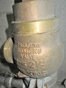 |
| (14) Unlike most PRVs, this Wilkins valve does not have a large rim. |
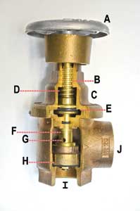
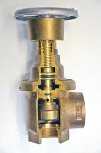
Photo 15 is a cutaway of a PRV that reveals the principal components: (a) manual valve wheel handle; (b) threaded stem; (c) upper bonnet assembly; (d) water chamber in upper bonnet; (e) piston assembly; (f) floating valve stem; (g) inlet hole for waterway inside the floating valve stem; (h) valve disk; (i) valve inlet; and (j) valve outlet.
 |
| (15) A cut-away of a factory-set PRV. |
In photo 16, it is important and interesting to note that the threaded stem and the valve’s floating stem are not connected; this is what allows the valve to float.
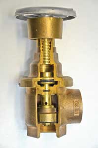 |
| (16) Note that the threaded stem attached to the hand wheel is not connected to the floating valve stem. This allows the valve to float in a range from fully open to fully closed. |
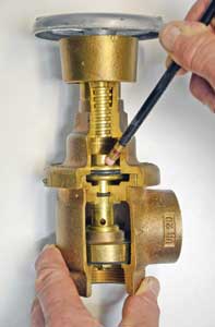
In photo 17, the valve’s hand wheel has been turned to the open position, moving the threaded stem upward and allowing water pressure to lift the floating valve off its seat. When the floating valve lifts off its seat, water enters the inlet hole for the waterway inside of what is, essentially, a hollow floating stem (photo 18). Water flowing through the floating stem fills a chamber in the upper bonnet assembly. This pressure, represented by the pencil, acts on the piston, forcing it in a downward direction. This, in turn, forces the floating valve partially closed, thus reducing the valve’s outlet pressure. The extent of force exerted by the piston and the extent of its pressure-reducing action depends on the valve’s inlet and outlet pressure and the piston’s surface area. A piston with a relatively large surface area will have a greater pressure-reducing effect than one with a relatively small surface area.
 |
| (17) The valve is opened at the hand wheel. The rising threaded stem allows the water pressure to lift the floating valve off its seat. |
|
| (18) Water entering the hole in the floating valve stem flows through a waterway in the valve stem filling the upper bonnet’s chamber with water. Pressure, represented by the pencil, exerts a downward force on the piston, which partially closes the valve, reducing outlet pressure. |
The two basic types of PRVs are factory set (photos 14-19) and field adjustable (photo 20). Factory-set PRVs are available with a variety of upper bonnet assemblies; each has a different size piston and its own pressure-reducing ability. For example, a factory-set PRV on the third floor will have a larger piston and more pressure-reducing effect than one installed on the 33rd floor. The surface area of a PRV’s piston in relation to the surface area of its floating valve’s disk provides a fixed pressure differential-in other words, although outlet pressures will vary with inlet pressures, outlet pressures will always be a fixed ratio or the same percentage of inlet pressures.
 |
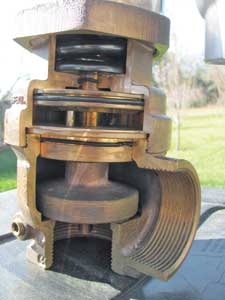
| (19) The valve’s hand wheel and threaded stem indicate that the valve is open, but it is actually closed because there is no water flowing. Water pressure downstream of the valve, represented by the pencil, exerts a downward force on the piston, closing the floating valve. This photo explains why PRVs cannot be back fed as inlets if an FDC fails. |
 |
| (20) A cut-away of a field-adjustable PRV that can be adjusted by tightening springs in the upper bonnet with a special adjustment rod. (Photo by Mac McGarry.) |
Photo 19 indicates the position of PRV components when the valve’s hand wheel is fully opened but no water is flowing. This would be the case when a hoseline connected to a standpipe outlet PRV is charged but is not flowing water. Photo 19 also indicates the position of components in a sprinkler system floor control PRV: The hand wheel and threaded stem indicate that the valve is open when it is actually closed. When no water is flowing, pressure downstream of the PRV rises, which in turn raises pressure on the piston, as represented by the pencil, forcing the floating valve to close. Photo 19 also explains why a PRV cannot be used as an intake in an FDC failure. It’s clear that pressurizing a ground-floor PRV will force the floating stem closed, similar to a check valve. If FDCs cannot be used on a building equipped with PRVs, an option that will work for most systems is to pressurize the fire pump’s test header (photo 21). This will necessitate gaining access to the fire pump room to open the control valve to the test header (photo 22).
 |
| (21) Supplying the fire pump test header if the FDCs fail in a building with PRVs. |
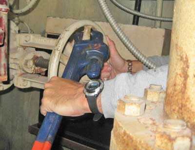 |
| (22) Supplying the system with PRVs through a test header requires accessing the pump room and opening the valve to the test header. |
Field-adjustable PRVs leave the factory with the same size piston. In some field-adjustable PRVs, the pressure-reducing effect is adjusted by inserting a rod into a collar in the upper bonnet that tightens a spring (photo 20). The spring works against the downward, pressure-reducing action of the piston, so tightening the spring has the effect of reducing the piston’s surface area and its pressure-reducing effect. Other field-adjustable PRVs can be adjusted by using a deep well socket to vary the depth of the threaded stem.
Companies in my battalion recently conducted a flow test in a 15-story building equipped with PRVs. First, our apparatus pumped into an FDC with two 50-foot sections of three-inch hose at 150 psi, the department’s standard starting pressure for standpipe systems. Personnel connected 200 feet of 1¾-inch hose to a first-floor outlet. Although we pressurized the system to 150 psi, the first-floor PRV reduced the discharge pressure at the outlet to 75 psi, which is dangerously insufficient for the 1¾-inch hoseline and a compelling reason to use 2½-inch hose for standpipe operations. The building’s suppression system’s contractor, who attended the flow test, advised us that 150 psi was insufficient because the building’s fire pump was designed to develop 222 psi. Taking this information into consideration, we increased our apparatus PDP to 225 psi for the remainder of the test. This pressure allowed firefighters to operate 1¾-inch and 2½-inch hoselines on the ground floor, the ninth floor, and the roof at proper operating pressures.
PRV NIGHTMARES
In a sense, PRVs simplify standpipe pumping operations because an FDC will be pressurized at one pressure regardless of what floor the fire is on. This pressure is required by code to be posted at FDCs (photo 23). PRVs that are properly adjusted, installed, tested, and supplied with their designed intake pressure are highly reliable, but they have been known to create nightmares for firefighters. What can go wrong with PRVs?
 |
| (23) An express drain riser facilities flow testing of PRVs. |
The primary problem is that they may not deliver sufficient pressure for supplying hoselines. This was experienced by firefighters at the tragic fire at One Meridian Plaza in Philadelphia, Pennsylvania. Low-pressure problems with PRVs are multiplied when firefighters operate from standpipes with 1¾-inch hose and combination nozzles that require a nozzle pressure of 100 psi.
Why would a PRV deliver insufficient pressure? First, consider that pressure in the lower portion of a standpipe riser is higher than in the upper portions because of elevation loss-hence, a PRV on the third floor would have a greater pressure-reducing effect than a PRV on the 33rd floor. Now imagine the effect of accidentally installing a PRV set for the third floor on the 33rd floor.
At One Meridian Plaza, PRVs were found to have been installed on the wrong floors. Remember that PRVs have a “floating” valve that spends almost its entire life in the closed position, opening only for a fire or a flow test that is required every five years. Consider the valves on a fire apparatus. What would be their condition if they were “exercised” only once every five years? To facilitate flow testing of PRVs, modern buildings are required to have express drain risers (photo 24) with a 2½-inch inlet at every floor. This simplifies flow testing because a PRV can be connected to the drain riser with a short section of hose. Testing PRVs without an express riser can be difficult, messy, and time consuming because water must be directed somewhere outside a building.
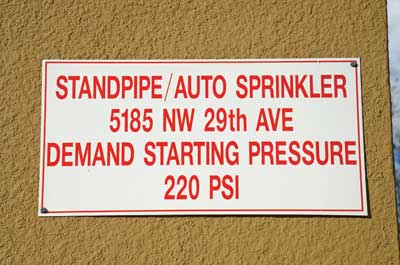 |
| (24) A sign posted near the FDC indicates a pressure to pump combination standpipe/sprinkler system equipped with PRVs. If the building’s fire pump fails, the fire department will have to pump 220 psi, even if firefighters were to use standpipe outlets on the first floor. |
SPRINKLERS INFLUENCE PROCEDURES
There’s no question that automatic sprinklers significantly improve the fire safety of a high-rise building and should be installed when a building is constructed as well as retrofitted in existing buildings. In Florida, condominium associations have lobbied the State Legislature to delay the mandatory installation of sprinklers in existing high-rise buildings until 2019. Although sprinklers improve the safety of both occupants and firefighters, they do require some consideration when revising high-rise fire SOPs/SOGs. For example, when a residential high-rise building is fully sprinklered, some building codes permit exit stairways to be as much as 400 feet apart. Increasing travel distance to stairways is a trade-off because a building is fully sprinklered, but it can significantly increase the amount of hose necessary to reach a fire. Firefighters are discouraged from connecting hose that is not located in a fire rated enclosed stairwell unless it is on the floor below a fire. Firefighters who connect a hoseline to a cabinet on the fire floor will follow their hoseline back to a cabinet that does not lead to their means of escape.
Now, consider an apartment fire in a fully sprinklered high-rise building with stairwells 400 feet apart. Since Murphy’s Law is in effect, we’ll locate the door to the fire apartment 150 feet from the closest stairwell. Connecting to a standpipe outlet on the floor below the fire can require as much as 50 feet of hose to reach the fire floor landing, and reaching the door to the fire apartment from the stairwell will require an additional 150 feet. Consider that it takes at least 50 feet of hose for a hoseline’s stream to reach any point in an average size apartment. That’s a stretch of 250 feet. Some building codes permit or require that standpipe hose outlets be on return stair half-landings. This can decrease the amount of hose necessary to reach a fire.
Sprinklers in elevator hoistways and machine rooms can complicate a fire department’s use of elevators during a high-rise building fire (photo 25). It is common knowledge that water is the nemesis of elevators. Water that finds its way into an elevator shaft will cause short circuits of interlocks and other electronic components, stalling the elevator. An elevator operated in phase II of fireman’s service is just as vulnerable to water as one in automatic operation. Elevators that are equipped with sprinklers have smoke detectors in hoistways to warn firefighters that sprinklers may operate, stalling the elevators. Activation of a smoke detector causes the fire helmet icon light on the elevator car’s control panel to flash (photo 26). This is a signal for firefighters to press the “call cancel” button and exit the elevator. If firefighters continue to use the elevator, they risk entrapment because heat detectors in the hoistway and machine room will actuate a shunt trip, shutting down the elevator prior to the operation of sprinklers.
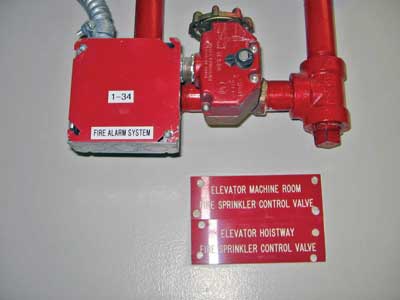 |
| (25) Valves controlling the sprinklers in an elevator hoistway and machine room. |
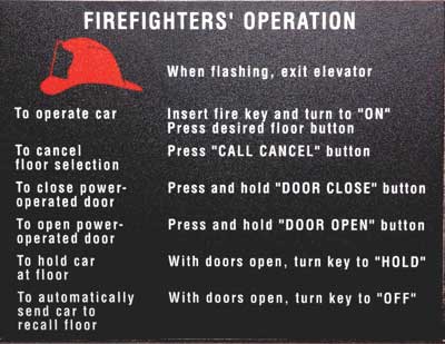 |
| (26) Smoke detectors in the hoistway or machine room activate the flashing fire helmet icon. Activation of heat detectors will actuate a shunt trip, shutting down the elevators before heat causes the sprinklers to flow. |
IMPACT-RESISTANT GLASS
Laminated impact-resistant glass consists of a layer of strong plastic between inner and outer layers of glass. Newer versions of impact-resistant glass are so strong that it is almost physically impossible to chop a hole of sufficient size to ventilate a building that may not have any windows that can be opened. Impact-resistant glass is not found just in areas subjected to hurricane-force winds; it is common in modern high-rise buildings throughout the country. Fire companies conducting prefire planning should ascertain if a building with impact-resistant glass has windows intended for ventilation that can be opened with a special key or a wrench. Impact-resistant glass is most effectively cut with a gasoline-powered saw with a carbide tip chain or blade. Unfortunately, gasoline-powered equipment doesn’t operate well in heavy smoke, so fire departments should consider the use of battery-powered circular and reciprocating saws to cut ventilation openings in impact-resistant glass. Battery-powered saws have nowhere near the power of the cutting speed of a gasoline-powered saw, so it is important to first “soften up” the glass by striking it with a tool such as a steel roof hook. Breaking the glass to outline the opening will significantly increase the cutting speed of a battery-powered saw because it will have to cut only the plastic inner layer, not the glass (photo 27).
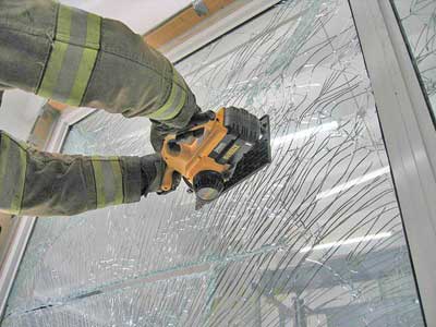 |
| (27) Firefighters practice cutting laminated impact-resistant glass with a battery-operated circular saw. Cutting with battery-powered saws will be faster if the glass is first “softened up” by striking it with a tool. |
TWO-INCH HOSE
Improvements in fire hose in recent years have made two-inch hose a viable alternative for 2½-inch hose for use in standpipe operations. Fire departments in Los Angeles, California, and Orlando, Florida, use two-inch hose with 1½-inch couplings. My department is currently testing two-inch hose with 2½-inch tapered couplings and evaluating its suitability for standpipe operations (photo 28). So far, the test results have been impressive: The two-inch hose will flow 250 gpm at a friction loss of 25 psi per 100 feet. Tests were conducted with a pitot gauge and flow meters. A pitot reading taken at a 11⁄8-inch smooth bore tip indicated a nozzle pressure of 45 psi and a flow of 250 gpm (photo 29). The two-inch hose with 2½-inch couplings approximates the flow of 2½-inch hose, but its weight and maneuverability are close to 1¾-inch hose. Will two-inch hose ever completely replace 2½-inch hose for standpipe operations? I hope not, because when we encounter a large volume of fire or critically low standpipe pressures, there’s just no substitute for 2½-inch hose.
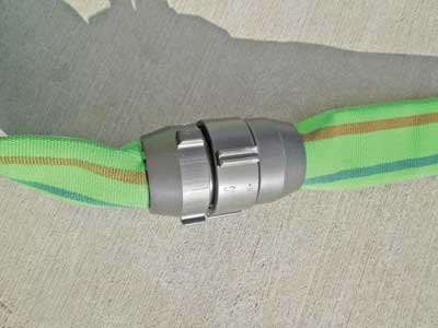 |
| (28) Two-inch hose with 2½-inch tapered couplings approximates the flow of 2½-inch hose and the maneuverability of 1¾-inch hose. |
 |
| (29) Two-inch hose with 2½-inch couplings flows 250 gpm through a 11/8-inch nozzle. The friction loss at 250 gpm is 25 psi per 100 feet. |
One compelling justification for 2½-inch hose is that standpipe systems in buildings constructed before 1993 were required to have a minimum residual pressure of 65 psi; they were not designed for hose smaller than 2½ inch and nozzles that operate above 50 psi. Two-inch hose may replace 2½-inch hose as a department’s primary standpipe hose, but every fire department that has responsibilities for high-rise buildings should be trained and equipped to deploy 2½-inch hose-and, most importantly, recognize conditions where there is no substitute for 2½-inch hose.
Thanks to Richard Avallone, Glenn Corbett, and Mac McGarry for their assistance with this article.
● BILL GUSTIN is a 40-year veteran of the fire service and a captain with the Miami-Dade (FL) Fire Rescue Department. He began his fire service career in the Chicago area and conducts firefighting training programs in the United States, Canada, and the Caribbean. He is a lead instructor in his department’s officer training program, is a marine firefighting instructor, and has conducted forcible entry training for local and federal law enforcement agencies. He is an editorial advisory board member of Fire Engineering and an advisory board member for FDIC. He was a keynote speaker for FDIC 2011.
Bill Gustin will present “Hoseline Operations for Fires in Multiple-Family Occupancies” on Wednesday, April 24, 1:30 p.m.-3:15 p.m., at FDIC 2013 in Indianapolis.
More Fire Engineering Issue Articles
Fire Engineering Archives

