Carbon Dioxide Fire Extinguishing Systems
Carbon dioxide is a proven firefighting agent that has been used in various applications since the early 1900s. The use of carbon dioxide tire extinguishing systems increased dramatically during World War II. when they were used to protect hazards aboard all types of ships Many Navy and commercial vessels today use such systems to protect machinery spaces. Power plants use CO . systems to protect large generators and transformers from fires. Manufacturing and chemical plants use them to protect equipment and processes involving flammable or dangerous materials.
It is important that firefighters understand the characteristics, advantages, and disadvantages of carbon dioxide and the types of carbon dioxide extinguishing systems that will factor into their size-up and operations.
CARBON DIOXIDE (CO,)
Carbon dioxide is an odorless, tasteless, colorless gas that w ill not support life. It is heavier than air and is a liquid when under a pressure of about 850 psi at room temperature, 70°F. (5860kPa at 21°C). When this pressure is released, the liquid gasifies, taking heat from its surroundings and producing extremely cold temperatures. Carbon dioxide once was used as a refrigerant, especially aboard ships during the World War I era, but lost favor because of the very high pressures required in refrigerating systems using it. Carbon dioxide can be frozen into a solid form, commonly called “dry ice,” in a press. In this form, it sublimates—goes directly from solid to gaseous form w’ith no intermediate liquid phase—hence, its name. Although CO will not support life, it is not toxic; the main threat to life is suffocation in high concentrations.
CO, AS A FIRE EXTINGUISHING AGENT
Carbon dioxide extinguishes fire by displacing the air that supplies oxygen for combustion. Its normal uses are Class B (flammable liquids) and Class C (electrical ) fires. Carbon dioxide also is used to a lesser extent on Class A (textile, wood, and paper) fires.
Advantages
This agent has several characteristics that make it valuable for fighting fires, particularly when used in automatic fire extinguishing systems. They include the following:
- It is not toxic. Minor leaks are not lifethreatening unless they are neglected to the point where the gas reduces the oxygen content of the space below the safe level.
- It requires no outside devices to gasify it or prepare it for use on a fire. Carbon dioxide liquid becomes a gas as soon as the pressure on the liquid drops, when it is exposed to atmospheric pressure; no mixers, proportioned, pumps, heaters, etc are needed.
- It acts as a coolant. Carbon dioxide becomes much cooler than ambient air when released; therefore, it provides some small cooling action on the fire.
- It does not leave a residue. Carbon dioxide is a gaseous agent that simply dissipates in the air, so it will not damageequipment.
- It is stored and transported as a liquid. The agent can be delivered by tank truck or in fully charged, interchangeable cylinders.
- It can be obtained almost anywhere in the world. Most developed countries haveplants that provide carbon dioxide.
- It is a well-known agent with familiar properties. The use of CO, should not produce environmental “surprises,” as has occurred with the halon agents.
Disadvantages
Carbon dioxide, however, does have some disadvantages, such as the following:
- When used to extinguish fire in a confined space by total flooding, it reduces the oxygen content to below a level that can sustain life.
- It is not effective on fires involving reactive metals (sodium, phosphorus, magnesium, etc.) or combustibles that supply their own oxygen (cellulose nitrate).
Comparison with halon as a firefighting agent
It takes a higher concentration of CO, than halon to put out a fire—greater than At percent by volume, as opposed to six percent by volume for halon. A rule-ofthumb figure for CO, is 63 lbs. (28.6 kg) of agent for every 1,000 cubic foot (28.3 m’) volume of the space to be protected.
C0 FIRE EXTINGUISHING SYSTEMS
The occurrence of a fire activates the automatic carbon dioxide fire extinguishing system, which applies enough CO, to fill the protected space to a 34-percent gas concentration, which will extinguish any fire within that space. Total flooding systems (discussed in this article) protect several spaces and direct just the right amount of gas to the affected area when a fire occurs. Some systems protect specific processes or pieces of equipment through the local application of C0. Most systems can be operated automatically, by fire detectors, or manually, by various triggering devices.
TYPES OF C0 SYSTEMS
The first developed carbon dioxide systems were high-pressure systems in which the agent could be stored only as a liquid under about 850 psi pressure at ambient temperature. This type of system is still used for some applications. The low-pressure system was developed after cryogenic equipment and refrigerating systems, w’hich made it possible to store the carbon dioxide liquid in large, refrigerated pressure vessels at a lower temperature, 0°F ( — 18° C), where the pressure needed to keep the agent liquid is only 300 psi (2068 kPa). The low-pressure system generally is used whenever very large quantities of carbon dioxide are required and the use of cylinders is a problem. The lowpressure system detects and operates in the same way as a high-pressure system, except that the liquid is stored in one container in the low-pressure system instead of in multiple cylinders.

TOTAL FLOODING SYSTEMS
Total flooding systems may be electrically or pneumatically powered. The basic characteristics of each system are given in box (opposite). The pneumatic type of system often is used to provide automatic lire protection for hazards that do not have electricity available.
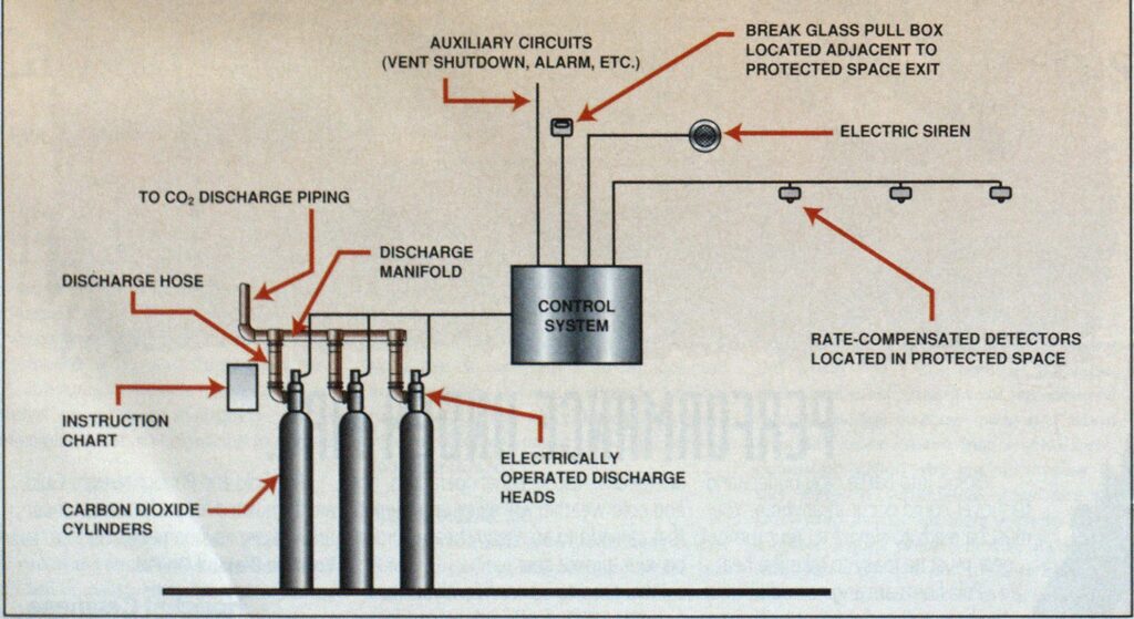
COMPONENTS OF FIRE EXTINGUISHING SYSTEM
Carbon dioxide tire extinguishing systems can be broken down into the following four parts:
- Fire delect ion—detects the presence of a fire and tells the system to operate.
- Operating system—sounds alarms, if required: performs some auxiliary functions (discussed later); and releases the co
- Agent storage—stores the carbon dioxide in liquid form.
- Gas-distributing system—-distributes the gas in the protected space or spaces.
Operation

Cylinder discharge head/discharge valve

FIRE DETECTION
An automatic fire extinguishing system detects the presence of a fire by detecting the light, smoke, or heat produced by a fire.
Flame detectors. These electro-optical devices are sensitive to the radiation in the bands produced by the combustion process in a flame. They are electrically operated and can interface with electric control systems. References 4 and 5 discuss how these detectors work.
Smoke detectors. Smoke can be detected by the standard photoelectric and ionization detectors in common use. which also are electrically operated.
Rate-compensated heat detector. This detector uses the motion produced by the difference in coefficients of expansion of metallic parts (detector casing and contact struts) of the detector assemblies when they are heated simultaneously.” This motion is used to close electrical contacts that actuate the release of C0 This type of detector operates slowly when compared with smoke detectors or rate-of-rise detectors. It also is less sensitive than rate-of-rise detectors. Its major advantages over other types of detectors are that it is less sensitive to changes in ambient temperature and that the contacts are hermetically sealed inside a casing, allowing the detector to be used in areas containing corrosive, explosive, or other adverse atmospheres.

Pneumatic rate-of-rise heat detector. With this detector, an increase in ambient air temperature produces a corresponding increase in air pressure inside an air chamber connected by a small tube to a special device in the operating system, called a “pneumatic control head,” mounted on the pilot cylinder, which supplies the power (carbon dioxide gas) to the operating system. The pneumatic control head triggers the operating system, a closed chamber with a flexiblediaphragm in one side and a small hole drilled in the chamber wall.
The rate-of-rise detector works in the following manner. When the temperature rises slowly, the air pressure in the system increases slowly, the hole allows the air to escape, and the diaphragm moves relatively little. On the other hand, if the temperature rises suddenly, as it would if a fire occurred, the air pressure rises too quickly for the hole to release it; the diaphragm then moves and opens the valve on the pilot cylinder, which releases the C0 therein into the operating system’s piping. The major advantage of the pneumatic rate-of-rise detector is that it does not require an external source of power as electric detectors do.
Manual operation. On some occasions, people working in the space protected by tlie system may notice a fire before it becomes sufficiently large to activate the fire detectors. Manual pull-box stations are provided outside the space near exits so the system can be set off by personnel as they leave. These pull-box stations arcswitches that close the discharge circuit tor electric systems or cable-pulls in a glass-fronted box. A system of tubes and pulleys runs the cable-pulls to the pilot cylinder’s pneumatic control head. When the glass is broken, as in the old-style firealarm boxes, and the handle is pulled, the cable mechanically opens the pilot cylinder valve, causing the system discharge sequence to begin.
THE OPERATING SYSTEM
Operating systems perform the following basic functions:
- Turn off ventilation fans that serve the space or stop machinery in the space. Carbon dioxide has to be in a 34-percent concentration to extinguish fires. It won’t work if it is being diluted by air blown into the space by the ventilation system or exhausted by machinery.
- Close dampers or doors to keep the gas in the space once the system has discharged.
- Sound alarms so personnel can leave die space before the system discharges. Since C0 can cause suffocation in concentrations sufficient to extinguish fires, personnel must be alerted to leave the space before the gas is admitted. The alarm is given by sirens powered by electric or C0 motors. A time delay prevents gas from being discharged until sufficient time has passed for personnel to evacuate the space.
- A time delay is included to give the alarms time to operate and personnel in the space time to vacate. An electric time delay is a standard time delay relay or circuit. The pneumatic time delay is simply a reservoir in the line from the pilot cylinder to the discharge heads. A calibrated tube tills the reservoir with C0. The resistance of the tube and the volume ol the chamber prevent the pressure in the pilot line from building up to a point where it can activate the cylinder heads until a specific period of time has passed.
- Trigger an external alarm system. The alarm makes it possible to call firefighters.
- Operate diverter valves in large systems. In large systems, a common CO; storage may serve more than one space. In such a system, the diverter valves direct the CO> to the space wherein the fire is located.
- Release the C0 from the storage tank/cylinders into the distribution system. On electrically activated systems, electric-actuated latching valves are used to initiate discharge. Pneumatic systems use C0-operated pilot valves powered by a small carbon dioxide cylinder, called the “pilot cylinder.” The valves on high-pressure cylinders are called “discharge heads.” Most manufacturers make the discharge valve integral with the cylinder the pilot devices that initiate dischargemanual. electric, or pneumatic—are interchangeable so that a single cylinder valve design can be used for any high-pressure system.
From the storage tank discharge valve or cylinder discharge heads, the liquid C0 goes to the system of piping and nozzles that distributes the gas through out the protected space. The CO, is liquid while in the system piping; it gasifies when it is discharged from the nozzles into the protected space.
AGENT STORAGE
Storage may he at high pressure in cylinders that come in several standard sizes or at low pressure as refrigerated bulk.
GAS DISTRIBUTING SYSTEM
The distribution system gets the C0 from the storage, where it is a liquid, to the nozzles in the protected space, where the liquid is turned into a gas and discharged into the space. The following components make up the distributing system:
- Cylinder manifold (high-pressure system). This consists of flexible hoses that connect the discharge heads to the manifold and a pipe suitable for the pressure of the C0 liquid. In the low-pressure system, the main runs directly to the storage tank.
- Piping from the cylinder manifold to the protected space, the main.
- Piping branches from the main to the nozzles.
- Nozzles that discharge the C0 throughout the space.
- Stop valves. A system that protects more than one space may have stop valves to control the admittance of C0to a space.
- A method for indicating the quantity of CO 2 in the storage. A scale beam is used to weigh high-pressure cylinders. The beam and hooks installed above the cylinders allow the cylinders to be weighed without being removed from the manifold. A low-temperature liquid level indicating system would be used with a lowpressure tank.
RECOMMENDATIONS
The following are some recommendations for dealing with CO, fire extinguishing systems:
- Consult established standards for the design and installation of these sys3.4 terns.
- After the system has discharged, thoroughly ventilate the affected space before anyone enters it. Breathing apparatus must be worn anytime anyone enters a space protected by a carbon dioxide fire extinguishing system that appears to have discharged. Ventilation will remove the carbon dioxide as well as any products of combustion from the fire, which may be toxic.
- Fire departments whose response areas include hazards protected by COj extinguishing systems should maintain an up-do-date listing of pertinent data on each system. Such a listing should include system location, hazard protected, type of detector(s), amount of C0 for primary discharge, amount of C0 for reserve discharge, volume of protected space(s), estimated time to completely ventilate with fans on first-in apparatus, maker of the C0 system, responsible party (owner/operator) of facility, and system manufacturer’s local service representative.
References
- Ansul Chemical Company sales literature.
- NFPA 12, Carbon Dioxide Extinguishing Systems, 1993 edition *
- CFR 46, 95.15. Carbon Dioxide Extinguishing Systems. Details *
- Cholin.J.M., “Flame Detection Basics, Part 1,” Industrial Fire Safety, Sept./Oct. 1993.
- Cholin. J.M . “Flame Detection Basics, Part 2,” Industrial Fire Safety, Nov./Dec. 1993.
* These references are standards for stationary and marine installations.

