<Previous Displaying 2/2 Page 1, 2
View Article as Single page
Lessons Learned/Reinforced
• Sprinkler systems have limitations. The size of sprinkler piping, the spacing of sprinkler heads, the gpm flow per head, and the number of heads expected to operate are all based on calculations of the heat produced by the commodity protected, the manner in which it is situated or stored, and the size of the anticipated fire area. Proper operation of a sprinkler system also depends on adequate minimum static and residual pressures. Change the commodity to one that produces more heat than the sprinkler system was designed for, increase the fire area, or reduce the pressure, and the system may fail to control a fire. Additionally, sprinklers, except deluge systems, are designed to control a fire in its beginning stages. At this incident, the fire was intentionally ignited while sprinkler riser control valves were closed. This allowed the fire to spread beyond the number of square feet the sprinklers were designed to protect. Once the valves were opened, water flowed from far more sprinkler heads than the system was designed to flow; consequently, pressure in the system dropped to a point that it was no longer effective. The lesson learned or reinforced at this fire is to recognize that it is important to ensure that the valves are open and to pump the FDCs as soon as possible. For fires in commercial buildings, FDCs should be pressurized before or simultaneously while advancing hoselines. At this fire, the deficit in water pressure and volume was at least partially overcome by the two engines supplying FDCs, but it was still insufficient to allow the sprinkler system to operate at its designed effectiveness.
• Most firefighters grasp the concept of fire load in terms of British thermal units per pound, but they may not have as thorough an understanding and appreciation of the concept of heat release rate (HRR). The HRR of the merchandise burning in the paint department was enormous, sufficient to distort large girder trusses and push out a tilt-up wall in less than 15 minutes from the dispatch of the first alarm.
• Another concept that may not be widely understood is interior collapse zones. Whereas exterior collapse zones are usually established at a distance from a building that is at least equal to the vertical height of a wall, interior collapse zones can be established where firefighters operate where load-bearing members are not damaged. It is, however, very important to understand that loads can shift from compromised structural assemblies and dangerously overload intact members. Redistribution of loads is a concept most accurately determined by a structural engineer or, at the very least, someone with extensive knowledge of building construction.
• Although tilt-up walls are commonly fastened in corners by welding steel imbedded in the concrete wall segments, this was not the case at the top of the A/B corner in this fire structure. This allowed the A wall to separate from the B wall. This fire taught a valuable lesson: Don’t assume that tilt-up wall segments will always be fastened with welded steel embedments.
Since fires in nonresidential/commercial buildings present a disproportionately high level of risk to firefighters as compared to civilians, you may question why firefighters would risk fighting fires in commercial buildings from the inside. Further, is the risk to firefighters to save property justified when there is no risk to civilians? The answer to these valid questions is that firefighters should not unreasonably risk their lives to save commercial property, but they are obligated to operate at a measured, acceptable level of risk, weighing the risk against the intended rewards. When a private dwelling is destroyed by fire, one family is devastated. When a fire destroys a commercial building or damages it to the point that business is interrupted, it can be devastating for several families because of the loss of income. Firefighters picking up from a nighttime fire in a business readily understand this when they see the look on the faces of employees coming to work in the morning. It is a look of shock and devastation; they realize that they no longer have a job. Unfortunately, this was the case at this fire. The store was torn down because it was decided that it did not generate sufficient profit to justify its repair.
BILL GUSTIN is a 41-year veteran of the fire service and a captain with the Miami-Dade (FL) Fire Rescue Department. He began his fire service career in the Chicago area and conducts firefighting training programs in the United States, Canada, and the Caribbean. He is a lead instructor in his department’s officer training program, is a marine firefighting instructor, and has conducted forcible entry training for local and federal law enforcement agencies. He is an editorial advisory board member of Fire Engineering and an advisory board member for FDIC. He was a keynote speaker for FDIC 2011.
Tilt-Up Wall Construction
By Fernando R. Fernandez
It is essential that fire officers understand the basics of the tilt-up concrete wall structure; its engineering, methods of production, and final construction. Understanding this will give you an insight into why and how the building will react under fire conditions or after a collapse, allowing you to make sound decisions on the fireground.
To better understand a building’s structural system, you have to grasp the concept of the building envelope, or what I call the “fire envelope.” Simply, the fire envelope consists of a skeletal system that transfers the loads to its foundation by virtue of its beams, walls, and columns (structural load-transfer points). Surrounding this skeletal system of the building is the outer surface-which I call the “diaphragm”-which can be constructed of various materials. The diaphragm can either be monolithically part of the whole structure or attached to the skeleton of the building. Either of these methods becomes a rigid and integral part of the structure, assisting with the building’s lateral forces as well as transferring loads to its foundation.
Tilt-up walls, also known as thin walls, have been in use since the early 1900s (particularly by the military), but they gained popularity in the 1950s. These concrete walls, sometimes cast on site and other times precast and delivered by truck, are tilted up into place. Although this method has been used for structures exceeding 90 feet in height, it is most commonly used for buildings under 40 feet. These walls are usually six inches thick and can weigh up to 150 tons. However, they must become proportionally thicker as the wall’s height increases. Although tilt-up wall construction is a structural system in itself, it may be incorporated with other systems such as a precast or a steel system.
Tilt-up wall systems are designed to sit on top of the footing and are held in place by raker shores until they are secured. Once leveled, they are grouted and welded together through steel embedded at predetermined locations, typically at the bottom, the seams, the corners, and the top (photos 1, 2). Once the roof system has been tied into the walls, the ground floor concrete is poured and the steel rebar left protruding from the bottom of the wall is tied into steel placed in the ground floor.
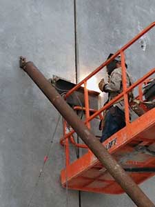 |
| (1) Steel is arc welded to the steel embedded in the tilt-up wall sections. Note that a raker shore is used to support the wall sections until they are fastened together and to the roof. |
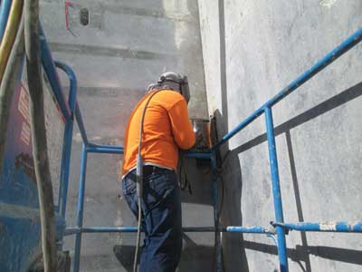 |
| (2) A steel angle is welded to the steel in the wall sections to fasten them in the corners. This apparently was not done in the A/B corner of the Home Depot where this fire occurred. (Photos by Bill Gustin.) |
When designing a tilt-up wall system, engineers must take into account not only the various loads applied to the structure but, equally as important, the reactions of this large volume, dynamic space, its components, and its connections as they are subjected to normal environmental and thermal conditions. Although rigidly tied together, the components must be able to move, contract, and expand. All structural members and connections must work together to create stability, ensuring that the structure is not solely dependent on one member. Concrete is inherently fire resistant; however, the tilt-up wall system is also dependent on fire protection systems or coatings to protect its structural components. It is this redundancy that reinforces the entire wall system and aims to prevent deterioration and a catastrophic collapse.
When approaching the building and establishing the proper fireground tactics for the conditions at hand, fire officers must perform a proper size-up, and care must be given to the location, extent, and condition of the fire; locating the fire department connections; panel distortion; separation or spalling as well as changes to the roof structure, establishing collapse zones, and proper apparatus placement. This is important because, as stated previously, the embedments, weldments, and rigid connections that hold the structure together are designed for normal loading conditions and environmental changes and not to withstand heavy fire conditions. It is important to understand that structural members supporting a roof, such as trusses, girders, and beams, may rest on a column or wall with as little as four inches of bearing surface.
Roof structural members bolted or welded at their bearing points are restrained from elongating when they are heated or cooled unevenly and have a tendency to warp and distort, which may cause them to pull off their bearing or connection points. Additionally, tilt-up wall sections can fail to the point of collapse when the concrete spalls as it reduces the strength of the embedments and weldments tying the wall sections together.
The Home Depot fire in South Miami-Dade County is a great example of the deterioration of a tilt-up structural system caused by extreme heat. This large-volume building was approximately 100,000 square feet and about 30 feet high. It was constructed using a tilt-up wall system for the exterior walls and an interior structural steel system that would assist in supporting a steel roof system with clear, interior, simply supported spans of up to 45 feet.
The roof system was comprised of steel open web joists topped by an expanded metal deck, lightweight insulating concrete, and a modified bitumen roof membrane. The open-web, steel roof girders were supported and attached to the interior steel columns and the tilt-up walls and spanned between the B and D sides. The open web joists were supported and attached to the girders and the tilt-up walls between the A and C sides of the building. The roof system was attached to the joists and an angle iron that runs the length of the B and D sides. As is typical, the tilt-up walls were stitched together vertically using steel embedments and welded plates, leaving about a one-inch caulked seam for expansion between panels.
After the fire and on review of the structure’s condition, one can conclude that while the fire sprinkler system was shut down for repairs, the fire quickly intensified because of the products stored on the rack and, as the fire progressed, the extreme heat created movement and expansion within the tilt-up structure. Soon thereafter, the heat and fire impingement on the girder truss caused the girder to deform and push outward toward the A side of the building. The force created by this distortion moved the joists attached to it toward the A side and applied a lateral force to the top of the tilt-up wall at the A /B corner. At that point, the A wall separated outward and away from the B wall.
As the fire continued, but prior to extinguishment, the A/B corner began to return to its original position, which may have caused the reformation of the wall. During the later stages of the fire, the joists directly behind the girder sagged; as they did, they pulled the already heated girder back, therefore, relieving some of the lateral forces on the A wall. Also, as the walls began to cool, they contracted and moved back inward.
Now, why did the A/B corner pull away and not affect the walls adjacent to it? On review of the A/B corner, from the inside, it was noted that there were no corner embedments or angles to tie the corner together; therefore, the simple connection of the metal deck to the angle iron on the B wall did not withstand the later forces imposed by the bar joists.
FERNANDO R. FERNANDEZ is a 30-year veteran of the Miami-Dade County (FL) Fire/Rescue Department from which he retired as assistant chief, second in command. He is a licensed general contractor and founded a company specializing in concrete construction. He taught high-rise operations to area departments in Las Vegas. He was a Federal Emergency Management Agency/Department of Defense logistical manager, a technical and logistics team manager and rescue specialist for Miami-Dade Task Force One, and a member of the United States Agency for International Development/Office of U.S. Foreign Disaster Assistance response team. He operated at the following urban search and rescue deployments: Punta Gorda (FL) Hurricane Charlie (2004), New York’s World Trade Center Attack (2001), El Salvador earthquake (2001), Turkey earthquake (1999), Colombia earthquake (1999), and Oklahoma City bombing (1995).
Fire Engineering Archives
<Previous Displaying 2/2 Page 1, 2
View Article as Single page

