Universal Friction Loss Formula
Most fire science students and pump operators eventually become familiar with the given formula used in determining engine discharge pressure for a given hose layout:
EP = NP + FL + BP
Where:
EP = engine pressure (pump discharge)
NP = nozzle pressure FL = pressure loss due to frictional effects in hose
BP = back pressure, or pressure due to difference in elevation between pump and nozzle
Here we have a fire fighter’s version of the Bernoulli equation, stating quite surely that energy in a hose line is neither created nor destroyed, but rather converted from one form to another. The formula is quite simple and can be mastered by even the most casual of pump operators.
Nozzle pressures specified for today’s fog nozzles are quite universally in the vicinity of 100 psi. A straight tip is ideally operated at 50 psi for a hand line, 80 psi for a master stream. This is simple enough. Back pressure can be quickly approximated at one half psi per foot (or 5 psi per story) of elevation difference—added if the nozzle is higher than pump discharge, subtracted if lower. Again, this is quite straight forward.
Alternative offered
The confusion begins, however, when the pump operator must determine friction loss. Many have sought out, and perhaps mastered, one of the several rule-of-thumb methods for calculating friction loss. This article is not to discourage the use of such methods but rather to offer for consideration a somewhat less simple but universally applicable (all hose sizes, all fluids) fire hose friction loss formula.
Around the turn of the century, there was a flurry of activity in fire service hydraulics with the development of improved equipment and methods. Today’s fire science student soon finds that while water supply appliances and equipment have improved immeasurably and specialized education of the fire service is now commonplace, some methods have remained at the turn of the century. The 2 1/2-inch hose was the mainstay of a turn-of-the-century fire attack team. Consequently, nearly all of the early hydraulics study was limited to this hose size.
Later as 1 1/2-inch, 3-inch and other sizes were introduced, the pump operator was encouraged to figure any given layout as if it were all 2 1/2-inch hose and then divide by a conversion factor or count on his fingers—or sometimes just guesstimate—to determine friction losses for these sizes. In addition, friction loss for 2 1/2-inch hose continued to be calculated by various rule-of-thumb methods which had been developed for the fire fighter of the early 20th century, who usually lacked formal education in his field.
Today, on the other hand, it is not unusual to find fire fighting professionals, both full-time and part-time, who have strong training and educational background in fire protection. Equipped with some basic math skills and some hydraulics training, many of today’s fire fighters are ready for a more analytical, based-on-facts, approach to determining friction losses.
Early in 1975, with the help of an interested group of in-service fire science students at Eastern Maine VocationalTechnical Institute in Bangor, Maine, the writer was able to develop such an approach. A single, easily used formula for friction losses, yet with the flexibility to handle all hose sizes, fluids, and units (metric included) was sought—a universal friction loss formula.
Derivation of formula
To find our formula, it was necessary to go back to the 19th century to a formula developed for design engineers, the Darcy-Weisbach equation for friction loss (head loss to engineers) in conduits such as pipe or hose:
hf = f L/D (V2/2gc)
Where:
Hf = head loss due to friction
f = friction loss factor, accounting for pipe roughness and complex properties of the fluid (notably viscosity)
L = length of conduit
D = diameter of conduit
V = velocity of fluid flow
gc = gravitational constant
At first glance, one would be tempted to leave this one to the engineers—too complicated. Further examination, however, reveals that for any given hose size and given fluid:
f is constant, or unchanging, with varying turbulent flows (all practical cases except when a friction reducing agent is used).
gc is a gravitational constant—unchanging on this planet.
D is our hose size—constant.
Substituting the factor C for the combined constants and our more familiar FL for the engineers’ hf, we get:
FL = CLV2 or CV2L
Velocity-flow relationship
The fire science student learns early in hydraulics training that velocity and flow are directly proportional by the relationship:
Q = AV
Where Q = flow
A = cross-sectional area V = velocity
Substituting:
V = Q/A
in our formula (remember that algebra class?) yields:
FL = C Q2/A2 L
Again, we can simplify by combining constants (A, or cross-sectional area, is of course relatively constant for a given hose size, varying slightly with pressure):
Let C/A2 = k,
Then FL = kQ2L, where we define Q as flow in hundreds of gpm and L as length in hundreds of feet—until metrication arrives at the fireground..
This is our universal friction loss formula. It states, simply, that friction loss is directly proportional to the square of flow (sound familiar?).
Limits for constant
Once a numerical value is determined for k, the value will be constant for all flows provided:
- The fluid is unchanged (water, oil, foam, slurry),
- The size and type of hose are unchanged,
- The units of flow and pressure measurement are unchanged.
Based on these turn-of-the-century experiments, a value of 2.4 was determined as the k factor for 2 1/2-inch, double jacket hose in 100-foot lengths, yielding:
FL = 2.4Q2L
This was simplified for 2 ½ -inch hose to the familiar:
FL = 2Q2 + Q
This is based on the approximate equality of 0.4Q2 and Q for common fire flows.
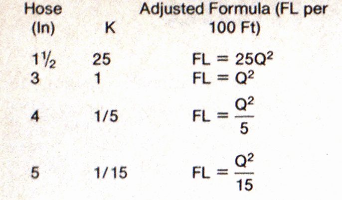
TABLE I
Friction Losses for Various Hose Sizes

More recent experimental results have indicated that the k factor for modern 2 1/2-inch hose is nearer 2.0. However, the significance of the universal formula is that any fire department can adapt it for its own particular observations, i.e., the k factor for its own hose can be determined on the training ground by test and used thereafter. The formula’s accuracy is comparable to that of the complex nozzle pressure equation or underwriters’ formula while it remains simple enough for fireground use—with practice.
Determining k value
As an example,of how the k factor is determined, let us examine the data provided by one manufacturer of 4-inch hose:

To determine k for this hose flowing plain water:
FL = kQ2L
For 1000 gpm:
FL = 20 psi per 100 ft
Q = 10 (hundreds of gallons)
L = 1 (100 ft)
Using basic algebra:
k = FL/Q2L = 20/(10)2(1) = 1/5
Our friction loss formula for 100 feet of 4-inch hose becomes:
FL = 1/5 x Q2 = Q2/5
The reader should calculate the value of k at 500 gpm and 700 gpm for experience and as a check.
Table I lists the k factor values determined in 1975 for common hose sizes based on data available from various sources at that time.
The above formulas are based on various tests performed over a period of 50 years or more. The important consideration, however, is that the reader, as a fire fighter or fire officer, can now develop the formula which applies to his needs.
For instance, let us consider a newly purchased attack line hose of the Progressive Fire Department. It has a 1 11/16-inch diameter with 1 1/2-inch couplings and is to be used with a fire-retardant agent proportioned at a constant rate. One morning of testing at the training ground has given the following data:

Using these results we find the k factor for our new hose flowing water with a fire-retardant agent.
k = FL/Q2L = 22.5/(2.5)2(2)
k = 1.8
Therefore, our universal formula for FL per 100 feet becomes:
FL = 1.8Q2
Checks should be made, using the other two flows.
For fireground use, we can simplify this to:
FL = 2Q2
If the hose were also to be used with plain water, more tests and determination of another k factor would be necessary since this would be a different fluid than that used in the original test.
Exception to rule
One cautionary cliche is offered: There is an exception to every rule.” The exception to our universal formula is that it does not apply to laminar, or nonturbulent, flow conditions. As this is written, the author is aware of only one fire fighting situation where turbulent flow is not achieved. That is when a friction-reducing agent is introduced into the hose stream, such as the use of Rapid Water in New York City. Friction-reducing agents function by delaying the change from laminar to turbulent conditions until very high flows are reached.
The f factor of the Darcy-Weisbach equation would not be a constant with laminar flow. The universal friction loss formula would not apply.
Friction loss tests conducted on the training ground would prevent the reader from applying this formula since the kQ2 formula would deviate severely from the test results; i.e., a different value of k would be found at each different flow.
This “new” formula appears more complex than some of the rule-of-thumb methods and therefore may not seem as universally applicable to pump operators as it is to hose. However, its advantages lie in its flexibility (any size hose, any fire fighting fluid, any units), its accuracy and its simple two-step computation for any size hose. There is no need to memorize conversion factors or carry a plastic slide rule.
Try the following example and several fireground examples from your own recent experiences. With practice, this method should become more easily used than the variety of rule-of-thumb techniques.
Example
Two engines arrive at a heavily involved rural dwelling. Three 1 1/2-inch lines, each 200 feet long, are pulled from Engine 1. Each line has a 95-gpm fog nozzle. Engine 2 lays a 4-inch supply line from Engine 1 to draft from a stream 700 feet away and 30 feet lower than Engine 1. Determine the proper engine pressure for each engine.
For Engine 1 (1 1/2-inch attack lines of equal length and flow):
FL = 25Q2 (Table I)
= 25 (100gpm/100)2 = 25psi
Therefore:
FL = 50 psi for the 200-ft lines
EP = NP + FL + BP
EP = 100 psi + 50 psi + 0
EP = 150 psi for engine 1
For Engine 2 (single 700-foot, 4-inch supply line)
FL = Q2/5 (Table I)
= 1/5 x (100+100+100/100)2
= 32/5 = 9/5 = 2psi
Therefore, FL for the 700-foot line is 2 psi X 7, or 14 psi, rounded to 15 psi.
Note that our “nozzle pressure” will be the desired intake pressure at Engine 1, 20 psi.
EP = NP + FL + BP
= 20 psi + 15 psi + 15 psi = 50 psi for Engine 2

