THE SMOOTH-BORE NOZZLE
HYDRAULICS
Fireground Hydraulics in Your Head:
Proficiency in the mental arithmetic of hydraulics will pay dividends on the fireground and in the boardroom.
In “Fireground Hydraulics in Your Head” (March 1989) I described a simple way to calculate friction loss in hose using only mental arithmetic. The system also can be applied to hydraulics of the smoothbore nozzle. Readers who haven’t been practicing mental calculations are advised to review and then work out examples on paper.
FLOW VARIATION WITH PRESSURE
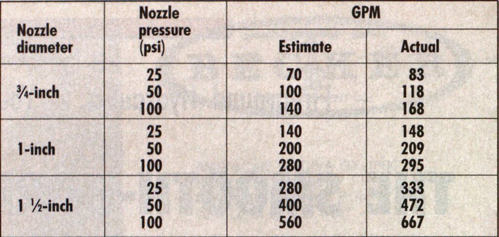
The flow rate (gpm) through any aperture with a fixed size, such as a smooth-bore nozzle or nonautomatic fog nozzle, varies approximately as the square root of the pressure at the nozzle tip or outlet (“tip” and “nozzle tip” are used interchangeably):
GPM varies as (Tip Pressure) or Tip Pressure as GPM2.
The square root of 2 is approximately 1.4, so if the pressure at the tip of a nozzle flowing 100 gpm at 12.5 psi is doubled to 25 psi, it will flow 1.4 x 100 gpm = 140 gpm, or 1.4 x 140 gpm = 200 gpm at 50 psi. In the same way, since the square root of 0.5 is approximately 0.7, a nozzle flowing 80 gpm at 50 psi will flow 0.7 X 80 gpm = 56 gpm at 25 psi (half the pressure). (Note that friction loss in hose follows exactly the same relationship: The flow rate in gpm varies as the square root of the friction loss in psi.)
How, then, can single-gallonage fog nozzles be given a single rated flow, say, 95 gpm? It’s a matter of pattern. Fog nozzles have the best pattern and reach at a tip pressure of 100 psi. That’s why flow calculations for fog nozzles assume “100 psi at the tip.” This is valid for all types—the old “single-gallonage,” noncontrollable automatics, and the advanced flowcontrollable automatics.
A smooth-bore tip has a different configuration. Water leaves in the form of a solid cylinder, unlike the hollow cylinder or conical form of the water leaving a fog nozzle (see illustration). The optimum pressure for a stream with most effective reach increases slightly with the diameter. Although optimal nozzle tip pressure for handheld smooth-bore nozzles is between 40 and 60 psi depending on manufacturer, size, and shape, for hydraulic calculations this is assumed to be 50 psi, in the same way that 100 psi is assumed for fog nozzle calculations.
HOSE CALCULATIONS
Consider 400 feet of 2 1/2-inch hose with a 1-inch tip. The desired tip pressure of 50 psi gives a flow of 200 gpm. (These are the only numbers you need to remember.) Friction loss in the hose will be 400 feet X 10 psi/ 100 feet, or 40 psi. The engine pressure equals tip pressure plus the friction loss, which in this scenario is 90 psi (50 + 40 = 90 psi). We can get much more flow than that, though. If the nozzle pressure is doubled to 100 psi (not recommended), the flow will increase by 40 percent to 280 gpm. Friction loss will double to 20 psi per 100 feet, or 80 psi. The engine pressure will then increase to 180 psi. Note that for the same nozzle tip and hose the flow rate also varies as the square root of the engine pressure: Doubling the engine pressure from 90 to 180 psi increases flow by 40 percent from 200 to 280 gpm.
NOZZLE TIP DIAMETER
Flow varies directly as the area of the tips for the same tip pressure. Since the bore area of a tip is (TT/4) X diameter2, if the tip diameter doubles, the flow will quadruple. For example, a 1-inch tip flows 200 gpm at 50 psi. A 2-inch tip will therefore flow 800 gpm at 50 psi; a 1 3/8-inch tip (about 1.4 inches) will flow 400 gpm; and a 3/4inch tip (roughly 1 inch/1.4 inches) will flow about 100 gpm. There is a simple way of estimating the square of a fractional number close to one. For example, (1 1/4)2 is equal to 1.25 x 1.25, which is approximately (1.250.25) X (1.25 + 0.25) = (1.0) x (1.5) = 1.5.A 1 1/4-inch nozzle tip will therefore flow about 200 gpm x 1.5 = 300 gpm at 50 psi.
The friction loss for 300 gpm through 400 feet of 2 1/2-inch hose is just over 20 psi per 100 feet, so the total friction loss is about 4 x 20 psi, or 80 psi. The engine pressure need only be 50 + 80 = 130 psi, compared with 180 psi for a 1-inch tip with the same flow. This is a definite improvement, particularly since the stream is now useful, giving much more effective reach than a “blowing” 1-inch nozzle tip at 100 psi.
The nozzle tip size should not significantly exceed half the hose diameter, otherwise effectiveness of the stream will suffer. The largest useful tip for 2 1/2-inch hose is therefore 1 3/8 inches. Using the approximately square method, it will flow 200 gpm x (1.375 x 1.375 ), which is approximately 200 gpm X [(1.375 – 0.375) x (1.375 + 0.375)) = 200 gpm x 1(1) x (1.75)] = 200 gpm x 1.75 = 350 gpm. The friction loss will be about 30 psi per 100 feet, so the engine pressure will be 170 psi. There will be a nozzle reaction of 125 pounds, so use a safe stance and open the nozzle slowly!
Comparison of Mental Estimates with Measured Values

To make life easier, mark or stamp the flow at 50 gpm (taken from tables) onto your handline nozzle tips and operate them at 50 psi.
EFFECT OF ELEVATION
All the previous calculations assume that the nozzle is at the same altitude as the pump. For elevated flows, every foot of rise produces a pressure loss of 0.4 psi. If a hose with an engine pressure of 100 psi is raised to the roof of a 25-story buildingassuming that each story is 10 feet high—no water will come out! Add 4 psi to the engine pressure for every 10 feet of nozzle elevation above the pumper or reduce the engine pressure by 4 psi for every 10 feet of depression if operating in a deep cellar, valley, or tunnel. This correction for elevation applies to any hydraulics situation—fog nozzles, relays, hydrant supply, and so on.
Let’s look at the case mentioned previously in which you’re flowing 350 gpm through 400 feet of 2 1/2-inch hose with a 1 3/8-inch nozzle tip. If the tip is on a ladder pipe, 60 feet above the pump’s pressure gauge, the engine pressure must be increased to 194 psi (60 feet X 0.4 psi/foot = 24 psi; 170 psi + 24 psi = 194 psi) to maintain 350 gpm. In this case it would be better to supply the ladder pipe with 100 feet of 2 1/2-inch hose and then run 300 feet of 3-inch hose to the pumper (using the method shown in my previous article, “Fireground Hydraulics in Your Head”). The pressure needed upstream of the 2 1/2-inch hose would be tip pressure + friction loss + height loss = 50 + 30 424 = 104 psi. A 2 1/2-inch hose with friction loss equivalent to the 3-inch hose would flow 350 / 1.7, which is approximately 200 gpm, so the friction loss in the 3-inch hose would be 10 psi per 100 feet. Engine pressure would then be 104 + (3 x10) = 134 psi, which is much easier on the pumper and gives it 40 percent more capacity. Note that 3-inch hose should always be fitted with 2 1/2-inch couplings for interchangeability. Additional friction loss is negligible. When operating 400 feet of 2 1/2-inch hose in a subway 50 feet underground, the engine pressure should be reduced by 50 x 0.4 = 20 psi to 170 – 20 = 150 psi.
REACH
As tip pressure increases, so does the reach of the stream. To double the reach, tip pressure must be roughly quadrupled —just like gpm and friction loss! Unfortunately, if tip pressure is raised above a critical value, the stream will “feather” and then begin to “blow,” at which point it is useless: The water will form spray rather than slugs that penetrate flame and get to the seat of the fire.
Effective vertical reach and horizontal reach are similar—about 70 feet at 50 psi for a 1-inch nozzle tip. The larger the tip, the longer the reach. The horizontal reach of a 1inch tip at 50 psi is 61 feet, increasing to 75 feet for a 1 1/2-inch tip —again, varying roughly as the square root of the diameter.
If at 50 psi you need more reach with the largest usable tip (half the hose diameter), have the pump opertor wind up engine pressure until the stream feathers and then cut it back a bit. That’s the limit of effective reach. More pressure will get less water where you need it.
NEW YORK HANDLINE
Now let’s analyze the famous FDNY light attack line. FDNY had previously used 1 1/2-inch hose with a 3/4-inch tip as an attack line. Let’s analyze a 200foot hose stretched to two floors (20 feet) above the pumper. At 50 psi, the nozzle will flow 200 x 0.5 x 1 = 100 gpm. The 2 1/2-inch hose with equivalent friction loss would flow 100/0.25 = 400 gpm for a friction loss of 40 psi per 100 feet. The engine pressure will be tip pressure + friction loss + height loss = 50 + (2 X 40) + (20 X 0.4) = 138 psi. To increase fire flow for increased effectiveness, FDNY switched to 1 3/4-inch hose in 1970. Existing 3/4-inch tips were reamed to the largest possible diameter, which was 15/16 of an inch. A 15/16-inch tip flows about 200 X 1 7/8 = 175 gpm at 50 psi. The equivalent 2 1/2inch hose will flow 175/0.4 = 450 gpm for a friction loss of about 50 psi per 100 feet. The new engine pressure is therefore 50 + (2 X 50) + 8 = 158 psi. This attack line is almost twice as effective as the old 1 1/2-inch line but weighs only one-third more.
Finally, let’s analyze the effect of using a standpipe. Suppose 100 feet of 3-inch hose is used to pump the standpipe and 100 feet of 1 3/4-inch hose is used inside the building. Friction loss in the 1 3/4-inch hose will be 50 psi. Friction loss in the standpipe will be negligible, as it will be in the 3inch hose flowing 175 gpm. The engine pressure will then be 50 + 50 + 8 (due to elevation) = 108 psi. The standpipe reduces engine pressure by 50 psi, so the hose is much tamer and pump capacity is increased.
The ability to perform hydraulics calculations gives a firefighter control over his most important tool — the hoseline. Calculating rather than guessing before buying fire equipment obtains direct monetary savings and more effective fire suppression — both of which lead to satisfied firefighters and taxpayers.

