By Jeremy Rifflard
Emergency shoring is the temporary support of structures during construction, collapse, or demolition. Shoring systems protect rescuers while working in a potential or confirmed collapse area. Shoring is a theoretical approach in which the shore acts like a funnel. The load above the shore is collected with headers and sheathing. The weight of the structure above is transferred through the posts and then distributed safely into the ground.
In a lean-to collapse, wooden or concrete floors that detach from one or both sides of their position and sag toward the ground are among the most dangerous of collapse situations. If the void space is less than four feet in height at the tallest area, cribbing is usually the preferred method of shoring under this collapsing upper level.
There are three classifications of emergency vertical shoring systems. A Class 1 shore aids in resisting compression with a post, but it has no protection from lateral or torsional loads. The most common class 1 shore is a T spot shore. Class 1 shores are temporary and should be replaced with permanent shores if significant entry time is needed.
Class 2 shores have two or more posts along a single header and sole plate. The posts resist compression as in a class 1 shore. Class 2 posts are braced along the axis of the header and sole plate to resist racking.
Class 3 shores are constructed from building two class 2 shores and installing them parallel to each other. After they are installed and pressurized, bracing is installed perpendicular between the shores to create a box.
Of the three shoring classes, a Class 3 shore is the strongest and most resistive to torsional forces. This is the permanent shoring system we should construct for extended operations.
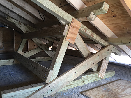
Type two and type three sloped-floor shore systems are used under sloping floors that are pinned to the floor on one side or hinged on one side with the slab floating above the lower floor (photo 1). To construct shores in either scenario, the void space should be in excess of four feet in height. The class 2 shores used in this kind of lean-to collapse are laced together to create a class 3 shore. Sloped-floor shoring systems are among the least frequently constructed and among the most complex technical rescue teams may have to construct. Learning a simple technique for constructing shores is beneficial to the safety of responding team members. Below is a technique that will help you overcome the fear of angles by creating a friction version of the sloped-floor shore.
Friction Version of the Sloped-Floor Shore
After measuring the height of the void space, clear an area on the floor of debris for the sole plate of your shores. The Federal Emergency Management Agency (FEMA) National Urban Search and Rescue Response System “Instructor Manual for Structural Collapse & Technical Rescue” emphasizes that, whenever possible, the sloped-floor shore should be prefabricated and brought into place.1 This friction method is the preferred method of installation in comparison with the built-in-place shore because it reduces the time the rescuer is in the precarious position of working under a leaning floor that is disconnected on one or both sides.
The complete class 2 shore is brought into place and then slid until it contacts the sloped floor looming above you. Fill small gaps with wedges where the shore does not contact the sloped floor above. The slight angle change that may occur when the post is driven tight should not affect the shore’s performance. (1) But, that is based on the rescuer’s getting the angles correct.
In January 2010, I was a team member of FEMA’s FL-TF2 and responded to the earthquake in Haiti. As a rescue specialist working for days in a three-story collapsed concrete structure, I can attest that when you are crawling with fractured concrete slabs above your head, you want to have as much shoring as possible protecting your travel path. Our team worked diligently to rescue seven live civilians who were heavily trapped in between concrete and steel. The irony of the situation was that the capital city had 100,000 fully or partially collapsed concrete buildings, but we could locate no lumber to use for shoring. The local forests had been harvested for use and were not replenished.
I have taught emergency shoring for several years to fire department and military search and rescue teams. Rescuers usually fully understand the two-post vertical shore. When the angles on the sloped floor posts are introduced, half of the class gives a blank stare. The iPhone-level app may show up under the sloped floor with a speed square. Students pivot the square and forget where to read the degrees or forget where the pivot point is for the speed square. Usually, one frustrated student sums up the experience by saying, “Somebody mark the post, and I will cut it.”
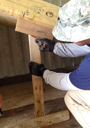
I have watched several good instructors teach the sloped-floor shoring system. I borrowed the best information from each lecture to develop a friction technique for creating the sloped-floor shore that is constructed without numerically measuring angles from the sloped floor to the posts. This process begins by creating a pivoting template (photo 2).
The Template
The template is built with two small pieces of a two-inch by four-inch lumber that is about 12 to 24 inches long. The third longer two-inch by four-inch piece is a length that fits under the sloped floor where the shorter of the two posts will be placed. One of those small two-inch by four-inch pieces is attached to the longer board on the end at a 90° angle to the post. It is secured with three nails or screws. The other end of the long two-inch by four-inch post will receive the second short piece of two-inch by four-inch lumber secured with one screw, which will allow this board to pivot.
Slide the template until it touches the underside of the sloped floor. Insert it with the pivoting end upward, and allow this end to adjust to the angle of the sloping floor. With a pencil, mark the angle of the pivoting board on the longer middle section of the template (photo 2). This is the angle at which the posts should be measured and cut. It does not matter how many degrees it is because in a later step, you will transfer the angle by laying this template onto your post. If you used a screw to attach this pivoting board, tighten the screw in place. If you used a nail, add an additional nail to prevent the angle from moving.
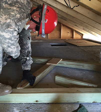
Locate the Posts
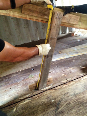
Determine the location of the posts for the shore. They should be three to four feet apart. Mark with a pencil the area of the floor where the posts should be located. Invert the template and place it on the post location you marked on the floor. You may want to use one rescuer to hold the template in place while a second rescuer measures the long side of the posts from the floor to the underside of the sloped floor (photo 3). The overall measurement minus seven inches will give you the length for your posts. The seven inches are deducted for the header and sole plates. This is not fully accurate, since the measurement is taken at an angle across the header and sole plate. As long as both posts are measured with the same method, the shore will fit snugly. Before you exit the collapse area, take note of tight hallways or turns. They may limit how much of the shore can be preassembled. The goal is to assemble as much as you can in the safe area.
Cut the Posts
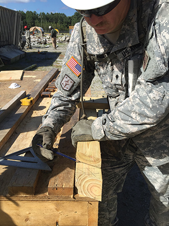
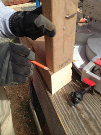
Now that you have your measurements for the length of the posts and the angle of the posts is marked on the template, remove the pivoting end from your template. You will be left with a two-inch by four-inch piece that has the correct angle marked on it. Cut this board along the marked line. You want the angle that was cut transferred on the posts, so lay the cut board on top of the four-inch by four-inch posts (photo 4).
Draw the angle on the posts, and cut them along that line. Remember, the cleat will need a 1½-inch return cut on the posts (photo 5). Now, use the long side measurement, and mark the posts. This is the 90° cut at the other end of the post.
Build the Friction Shore
Now that you have completed the post preparation, you are ready to assemble each class 2 shore. If your posts are four feet apart, use a six-foot header with a one-foot overhang on each end. Mark the header where the long side of the posts will be attached, and toe nail the posts into place at a 90° angle to the header. You can use the speed square to verify the 90° right angle.
Align the sole plate with the header on the end that has the shorter posts. The sole plate should be about two feet longer than the header on the end near the longer posts to account for the angles, cleats, and anchoring. Attach the angled end of the posts to the sole plate (photo 6). Double check your measurements to maintain the four-foot distance between the posts, and toe nail them into place. On the sole plate, place an 18-inch two- × four-cleat behind the posts with a proper 11-nail pattern. Add two-foot by six-inch diagonals to create an “X” pattern. Add half gussets to complete the construction of the first shore. Complete the second shore in the same manner. Before you take the shores into the collapse area, drill two holes through the longer sole plate to allow for the shores to be anchored. A four-inch length wood drill bit that is slightly wider in diameter than the anchor pin will suffice. You can use an alternate anchoring technique similar to that of raker shores with a perpendicular anchor behind the sole plate and then pressurize with wedges.
Installing the Shore
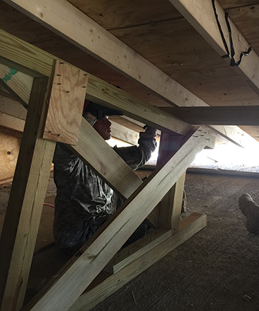
You have constructed a class 2 friction shore that will be slid into place. If the sloped floor is hinged to the ground, install the longer sole plate downward. Pin the shore to the ground with rebar. Use construction epoxy to prevent the rebar from moving. Use two-inch by four-inch wedges to fill any gaps. Lace the two shores into a single class 3 shore using a technique similar to that of constructing a laced post shore.
If the low side of the collapsing sloped floor is not touching the ground, install the longer sole plate upward. (Now, it is a long header, and you are installing a type three shore). Pin the longer header to the ceiling using anchors appropriate for the material from which the floor is constructed. Wood-frame floors will take a lag bolt. Concrete floors may take wedge anchors or rebar rods with epoxy. Fill the gaps on the floor with two-inch by four-inch wedges to keep the header snug to the sloped floor (photo 7). Turn these two class 2 shores into a class 3 shore by lacing them together.
Sloped-floor shores are among the most complex shoring systems for technical rescue teams to construct. They are not constructed often; therefore, we should know a more simple way to build and install this shore, such as the method described here.
Endnote
1. The method described is based on Module 2B slide 46 of FEMA’s National Urban Search and Rescue Response System Instructor Manual for Structural Collapse & Technical Rescue. (2012), Structural Collapse Training, Version 3.1.
JEREMY RIFFLARD has been a Florida firefighter since 1991. He is a captain with the Fort Lauderdale (FL) Fire Department, an officer of its technical rescue team, and a rescue squad officer of FEMA FL-TF2. His most recent deployments were to the Haiti Earthquake and Hurricane Ike. He teaches technical rescue programs for the Coral Springs (FL) Fire Academy. For the past 10 years, he has been an instructor and a safety officer for military urban search and rescue exercises.
Tech Rescue: Shoring Operations
Sloped Floor Shoring Systems
Wood Shoring Systems: How Do They Perform?

