Compressed-Air Foam Mechanics
CLASS A FOAM: AN EMERGING TECHNOLOGY
Compressed-air foam systems (CAFS) originated in the 1940s, but only recently has this technology been considered for extensive fire service use. The advent of the new generation of Class A foam in the mid-1980s and subsequent efforts to maximize its applications have been a vehicle for the growth of CAFS technology for municipal and forestry firefighting. As CAFS is quite different from conventional foam-generating systems, examining the physical laws governing the technology can help eliminate some of the mystique. Let’s discuss foam production mechanics, finished-foam properties, and fireground uses of CAFS.
CONTROLLING THE BUBBLES
Most municipal firefighters can relate to the use of mechanical foam concentrates. Typically, a municipal pumper carries a proportioning device (usually an eductor), a foam-generation device (usually an air-aspirating nozzle), and a stow of mechanical foam concentrate (AFFF, etc.). Using the eductor to proportion foam concentrate into the water flow creates foam solution; adding air and turbulence at the nozzle will create a finished-foam blanket as both foam and air exit together from the foam tube. The finished-foam blanket will have certain qualities, such as 25-percent drainage time, radiant heat resistance, viscosity, cohesiveness, and chemical reaction with the fire hazard.
The qualities of the finished-foam blanket and its behavior under fire conditions are determined in great measure by the foam’s bubble-structure makeup—bubble sizes, bubble shape, percentage of foam solution converted into bubbles, and bubble film thickness. In a conventional airaspirated foam generation system, the bubble makeup is a function of
- hydraulic horsepower (energy) utilized to push the foam solution through the nozzle; and
- the quantity of turbulence that takes place as the air and foam solution mix and exit the nozzle barrel (the nozzle design, including nozzle expansion ratio).
Compressed-air foam systems also rely on hydraulic horsepower and turbulence, but with CAFS, the amount of horsepower and turbulence (called “scrubbing”) is increased manyfold because of the addition of compressed air. The CAFS scrubbing process produces a finished-foam blanket that will have an entirely different bubble structure. It has been observed that the CAFS finished-foam bubble structure has its own unique “thumbprint” of small, tighdy packed, cohesive bubbles that causes the finished-foam blanket to behave differently than finished foams produced via air-aspirating nozzles.
Hie fireground advantage of using a CAFS is that by utilizing this unique bubble structure and modulating the air-tofoam solution volumetric ratio to control foam quality, the firefighter has the capability to manufacture a variety of finishedfoam blankets of different temperaments to maximize manual fire combat capabilities for various tactical operations.
The differences between the CAFS and conventional foam bubble structures are clarified by an understanding of “hydropneumatics.”
HYDROPNEUMATICS
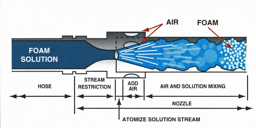
In simplest terms, creating foam using either a conventional nozzle-aspirated system or a CAFS requires the input of water, foam concentrate, and air. Assuming that foam proportioning has been accomplished through some method of integrating foam concentrate with fireground water, a conventional apparatus fire pump would propel the foam solution through a hoseline to an air-aspirating nozzle. As the foam solution increases velocity by moving through a stream restriction in the nozzle, air is entrained in the foam solution because of an air-pressure differential generated by hydraulic kinetic energy. As the air and foam solution exit the foam tube, some turbulence results. This creates the bubble structure and the finishedfoam blanket.
In a CAFS, the foam solution is propelled toward the discharge by the apparatus fire pump. At some point, compressed air (generally at 80 to 120 psi) from an onboard air compressor is injected into the foam solution in the apparatus piping. As the air and foam solution move through a mixing chamber and/or a specific length of hose, a large amount of turbulence (scrubbing) takes place under residual hoseline pressure. If there is a sufficient foam concentrate proportion within the water, small uniform foam bubbles are created by the scrubbing action and the bubbles are propelled out of the nozzle.
The foam discharge has propelling energy from the apparatus fire pump (hydraulic energy) as well as front the air compressor (pneumatic energy). These added together equal the governing force at work: hydropneumatics. Hydropneumatic scrubbing transforms the foam solution into a finished foam having a unique bubble structure that can be tactically matched to the fire challenge—an obvious advantage over conventional finished foam produced from an air-aspirating nozzle.


Factors ultimately controlling how the unique bubble structure of the CAFS finished-foam blanket behaves include hoseline pressure and the level/duration of scrubbing in the mixing chamber and/or the length of hoseline as it is produced. However, the primary variable governing the type or quality of CAFS finished foam (such as 25-percent drainage time and i radiant heat resistance) is the air-to-foam solution volumetric ratio used.
AIR-TO-FOAM SOLUTION RATIO
The air-to-foam solution ratio graph depicts types of foam produced at different volumes of air and solution. Foam type is determined by observation and reference to the qualitative characteristics of foam found in the colored boxes below the graph. The chart assumes a certain level of air-to-foam solution scrubbing and adequate foam concentrate percentage in , the foam solution, both of which are needed to create a foam bubble structure.
So, for example, a 100 standard cubic feet per minute (scffn) of compressed air and a 100-gpm foam solution ratio mix (1 gpm:l scfm) will yield a “type 5” finishedfoam quality. As you move down the righthand side of the graph, the ratio of compressed air-to-foam solution becomes greater and the foam consistency or “type” changes dramatically. Varying the ratio of air to foam solution to produce “wet,” “medium,” or “dry” foam types is the primary procedure used to create finished foams with different dispositions for various fireground tactical uses. The secondary means of fine-tuning foam type is to alter the foam concentrate percentage within the foam solution.
Note that the foam types produced in the graph are formulated by focusing solely on the air-to-foam solution ratios and do not take into account other variables such as scrubbing/foam concentrate quality and quantity—thus, they are generalized guidelines. A more effective way to quantify foam type is to analyze the drainage rate of the foam solution within the foam bubble mass. The most important field measurements found to quantify foam types are 30and 60-minute drainage-period tests.
.TACTICS
By utilizing various foam concentrates ^manufactured for specific fire hazards and through understanding CAFS foam production and applications, the versatility of CAFS can be applied in different fireground situations. For example, using
CAFS and AFFF at a 1 gpm: 1.5 scfm ratio for direct attack provides a fluid type #4 foam that has excellent flammable liquid fire knockdown performance. To safeguard the extinguished flammable liquid from reignition, a rigid, slow-draining AFFF finished foam can be formed by using a 1 gpm:3 scfm ratio. This will produce a tough, cohesive type #2 foam blanket with superior insulating/burnback resistance and much longer 25-percent drainage time, providing desirable vaporsealing performance.
Field successes using CAFS and Class A (synthetic detergent hydrocarbon surfactant) foams in wildland-urban interface and structure fire operations are numerous. Using a 1 gpm: 1 scfm ratio with Class
A foam concentrate proportioning at 0.3 percent forms a quick-draining type #5 foam blanket that expands the surface area of water to absorb available heat and drains quickly into ordinary combustible materials to provide efficient cooling. One empirical direct attack structure fire suppression test of type #5 CAFS foam showed that it was 480 percent more effective in ability to lower room temperature when compared with the same volume of plain water.
Using a Class A foam concentrate proportioning ratio of 0.3 percent and a 1 gpm:3 scfm ratio, a slower-draining type #2 foam blanket containing less water will be formed. Type #2 foam can be tactically utilized for structure exposure protection on glass and metal surfaces because of its adhesion capability and insulating qualities. In one scientific CAFS exposure protection test, a ¼-inch-thick layer of 14:1 expansion-ratio CAFS foam exhibited an ignition-inhibiting capability twice that of an equal mass of water for Tl-11 plywood siding irradiated from an external source. The compressed-air foam also displayed a retention efficiency approximately 20 times that of plain water on test samples.


AIR/FOAM SOLUTION COMPRESSABILITY

ONE GPM/ONE SCFM RATIO UNDER AMBIENT CONDITIONS 60°F, 14.696 PSIA (1 ATM)
ONE STANDARD CUBIC FOOT OF AIR (1.00 FT ONE GALLON OF FOAM SOLUTION (0.13 FT

ONE GPM/ONE SCFM RATIO UNDER 102⅛ PSIA (7 ATM) HOSELINE PRESSURE @ 60“F
ONE STANDARD CUBIC FOOT OF AIR (0.14 FT ONE GALLON OF FOAM SOLUTION (0.13 FT)
This chart reflects the typical one GPM/one SCFM direct attack CAFS hoseline ratio at both atmospheric and seven atmospheres pressure. Notice how the volume of air, when compressed to seven atmospheres, is 1/7 its original volume and accounts foi approximately half the CAFS hoseline volume causing a weight reduction of about 5⅜%.
(Courtesy of Hate Fire Pump Company)
HOSELINE WEIGHTS
Manipulating the CAFS hoseline by adjusting static and residual air pressure and flow can provide an added firefighting benefit of increased discharge distance for a given foam solution flow. Nozzle reaction force using CAFS is a function of not only water flow and tip size/style but primarily static/residual air pressure and flow. Adjustments can be made to increase or decrease nozzle reaction force to suit the nozzle operator and/or yield the best fire stream reach for the fire problem at hand.
Because the CAFS hoseline is filled with a percentage of compressed air, it will weigh less than if filled with plain water. The specific reduction in CAFS hoseline weight is directly related to the air-tofoarn solution ratio and the hoseline pressure. Some firefighters misinterpret the CAFS direct attack 1 gpm:l scfm ratio formula (which, volumetrically, is 7.5:1) and presume the CAFS hoseline weight will be lighter by a 7.5:1 ratio. This would be true if the hoseline were operated at atmospheric pressure (14.7 psi). However, a typical CAFS hoseline is operated at 100 psi and at times may be operated in the range of 80 to 120 psi. Because creating CAFS finished foam requires compressing air, Boyle’s Law—the law describing the behavior of gases—enters into the equation. Air is a compressible medium and will lose volume when placed under increased pressure.
Boyle’s law states: “If the temperature is kept constant, the volume of a gas will vary inversely as the absolute pressure, while the density will vary directly as the pressure. Since the pressure and volume of a gas are inversely related, the higher the pressure, the smaller the volume, and vice versa.” (Note, however, that Boyle’:! Law by definition is exactly true for ani ideal gas. It is obeyed only approximately ’ by real gases and is not a fundamental law such as Newton’s Law.)
The air/foam solution compressability schematic shown depicts one standard cubic foot of air and one gallon of foam solution at atmospheric pressure. As the’ air and foam solution are compressed, the volume of foam solution remains the same. However, with each atmosphere of pressure—or 14.7 psi—added, the volume of compressed air is reduced by a directly proportionate factor. Therefore, at 102.9, psi (under seven atmospheres of pressure), the volume of the compressed air will be reduced by a factor of ⅝ and the actual air volume will be slightly over the same volume of foam solution. Thus, a CAFS hoseline flowing a 1 gpm: 1 scfm ratio at 102.9 psi residual pressure isapproximately filled with 48 percent foam solution and 52 percent compressed air (assuming the air temperature remains constant) and will be lighter by a factor of 52 percent compared with a handline filled with plain water. The perception that the hoseline is filled with a high volume of air and very little foam solution (and thus an inadequate volume of water) is false.
Another CAFS perception is that compressed air somehow is extinguishing the fire. The volume of compressed air used in CAFS will not take the place of water in fire extinguishment. Used in conjunction with Class A foam solution, it will transform plain water into a desirable fire extinguishing medium by creating a foam bubble film, thus increasing the available water surface area to absorb heat. It also will create a foam bubble structure that adheres to three-dimensional ordinary combustible fuel geometry. This provides temporary vapor sealing and also will keep the foam solution on the fuel, allowing time for it to cool the material by penetration or evaporation until it is all gone.
CAFS can be a powerful fire suppression tool when utilized correctly. It can extend fire suppression capabilities of water supplies for direct attack and improve exposure protection. It can be used to govern the drainage rate of a finished-foam application so that less runoff is generated during haz-mat mitigation. It can reduce flame knockdown times, increase fire stream reach, and provide lighter-weight hoselines, all of which increase firefighter safety through stress reduction.
Scientific, empirical, and anecdotal evidence shows that CAFS can significantly extend the capabilities of Class A and Class B foam solution applications in municipal and forestry’ firefighting operations. However, before the technology can be utilized to its potential, an understanding of CAFS principles and methodology, coupled with intensive training, is essential. The benefit of CAFS technology, like any firefighting concept, is directly proportionate to the knowledge of the user.*
Endnotes
1.Marx, M., M. Harper, and T. Halter, “Introduction to Quantitative Modeling of Fire Fighting Foam” (Computer Integration and Literacy Institute, 1988).
2. Colletti, D., “Quantify ing the Effects of Class A Foam in Structure Firefighting: The Salem Tests” (Fire Engineering, February 1993).
3. Madrzykowski, D., “Study of the Ignition Inhibiting Properties of Compressed, Air Foam” (U.S. Department of Commerce, National Institute of Standards and Technology, October 1988).

