Radio I.Q.
FEATURES
COMMUNICATIONS
The most expensive solution to your radio communication problems isn’t necessarily the smartest.
Radio communications equipment is so commonplace in the fire service that we tend to take it for granted. When we do think about the huge number of options we face in choosing the full range of equipment, we may feel a bit overwhelmed at being asked to make important technical decisions in a field outside our own areas of expertise.
We can add to our understanding of what’s required to send and receive clear transmissions by taking a look at just three elements— the broadcast antenna, transmitter power, and radio frequencies.
But first, we need to know a couple of important facts about radio waves. Radio waves are emitted by radio transmitters at frequencies of millions per second, or megahertz (MHz). The frequency ranges the fire service most commonly uses are:
- 38 to 40 MHz;
- 153 to 155 MHz; and
- 453 to 460 MHz.
(There are some fire department radio systems that are operating in the 800-MHz region, but at this time the numbers are few.)
Radio signals have a lot in common with light waves. They bounce around, curve around, and penetrate matter in a manner very similar to light—in fact, they pass through some materials more readily than light does.
Not all radio waves pass through the atmosphere in the same way, however. Given the same amount of transmitter power, and identical antenna types and heights, some radio waves are more likely to bounce off certain layers of the atmosphere than others. Much of the bouncing is predictable, just as the actions of a skillfully hit ball are in a racquetball court. But not all of the bouncing is predictable, and that fact plays a crucial role in choosing the most appropriate combination of radio equipment for your communications system. Let’s see why.
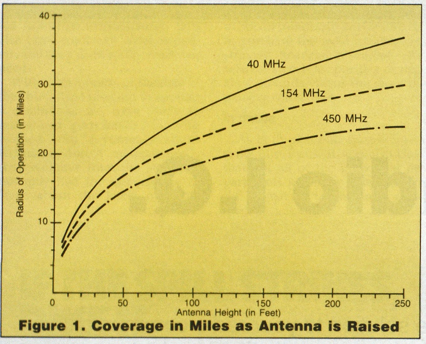
In Figure 1 (page 36), using identical transmitting power and other equipment, we can see that a radio frequency of 40 MHz provides the most complete coverage by radio signals at every antenna height we might choose. That advantage grows even greater as the antenna is raised, although each additional boost in the antenna’s height provides less additional coverage—whatever frequency we choose.
Decreasing gains in coverage are one of two reasons why increasing your transmitter’s antenna height indefinitely isn’t feasible. The other is that when radio systems are close together geographically, higher antennas make it more likely that a distant transmitter operating on the same frequency will interfere with the local base station receiver. In practical applications, antennas can’t be raised beyond the height that would allow another, nearby station to interfere with your own radio communications.


In Figure 2, we’re at the crucial point of our discussion, following both the predictable and unpredictable paths of the radio waves our antenna is transmitting.
The predictable paths are those of groundwaves, which travel essentially in a straight line from the antenna to receivers. Skywaves, on the other hand, act much as their name implies—bouncing off various layers of the atmosphere or even heading off into interplanetary space.
Skywaves are particularly troublesome in radio’s lower frequencies, which is why 40-MHz systems are often plagued with random, unpredictable interference from distant—even very distant—stations, especially during changes of season and in the presence of unusual weather fronts. The 154-MHz systems are less susceptible; the 450-MHz systems, even less so. Radio waves at these higher frequencies are more likely to pass directly through the various layers of the atmosphere and aren’t “bounced” back as often.
Only groundwaves are actually considered in the choice of virtually all local fire department radio communications systems. This is because reliability and predictability are so necessary.
Comparing solutions
Now that we know a few basics with regard to frequency and antenna height choices, we can examine the options offered in a practical situation.
Assume that in a real system, a transmitter operating at 100 watts of power is broadcasting from an antenna 100 feet above ground, and the general radius of field operations is about 22 miles. Complaints about the system’s reliability beyond 20 miles are now taken seriously because the field of operations is expanding to 25 miles as the area becomes more heavily populated.
Faced with the need to extend the effective signals out to 26 or even 28 miles, your staff members suggest these three possible solutions: Increase the transmitter tower and antenna height; double the power of the transmitter to 200 watts; or change the type of antenna that sends out your radio signals.
Figure 3 illustrates what’s required to implement the various choices:
- Curve 1 shows how the existing, 100-watt system operates if the antenna height is changed. To obtain reliable service at 27 miles, the tower’s height would have to double from 100 to 200 feet.
- Curve 2 shows the implications of doubling your transmitter’s power to 200 watts, a power level not common in the fire service. The purchase itself would be the easiest part of this approach. However, the FCC would have to approve any power increase before operation could start, and that takes time. Again, the tower height would have to be increased, in this instance from 100 feet to 150 feet.
- Curve 3 takes the approach of choosing a different type of equipment, using what’s known as a “gain” antenna instead of the “quarter-wave” antenna common to many systems.
Raising an antenna is always an expensive choice, particularly if the tower isn’t self-supporting. With a 100-foot tower, the guy wires are anchored approximately 80 feet from the base of the tower; with a 200-foot structure, the supporting wires are anchored about 160 feet away. That might require purchasing additional real estate at the base of the tower, which could be very expensive.
Further, permits from the Federal Communications Commission and other agencies might be required to raise the tower height; the Federal Aviation Administration may have additional restrictions near airports and flight paths.
Though these approaches achieve strong, reliable coverage to 27 miles, both deal largely in choosing, in effect, more of the same equipment at substantial expense and with the possibility of delays waiting for various approvals from other agencies. By requiring more tower height, both also invite—and are apt to cause—distant signal interference.


Take a look at Figure 4 (page 37), and we can see the differences between these two types of antennas. The quarter-wave antenna broadcasts its signal with equal power in all directions, as the two circles radiating from the top of the antenna indicate. That pattern of signal radiation contributes heavily to skywaves—those signals that don’t serve to improve our communications and may indeed help set up “bounced”-signal interference.
By contrast, a gain antenna is designed to “squirt” the signal into a predominantly horizontal pattern which results in more groundwaves and fewer skywaves. The gain antenna concentrates the radio signal into areas where it will be most effective, much the way a spotlight works when compared to a regular light bulb of equal wattage.
The ability of a gain antenna to squirt or flatten its radiated signal is expressed in technical terms as a decibel, or db, which represents a mathematical relationship between the effective power of a quarter-wave antenna and the apparent effective power of the gain antenna. The symmetrical signal generated by the quarter-wave antenna is the standard of comparison with gain antennas and their ability to squirt radio signals into these flatter, asymmetrical patterns.
Each time the “db” increases by 3, the power increases by 2. (See Figure 5, page 37.)
The comparison is illustrated graphically in Figure 6 (page 37).
Now that we know this process makes the radio system appear to have more power than it really does in designated areas, we can go back to Figure 3.
When we examined the choices indicated in Curves 1 and 2, we found them likely to be expensive and subject to both time delays and unwanted new problems with interference.
On Curve 3, we find that using a 6-db gain antenna increases our 100-watt transmitter’s effective power to 400 watts, allowing us to provide reliable signals to 27 miles, which achieves the goal we set of having a good signal to at least 26 miles.
By changing the type of antenna, we can achieve at far less cost what we had otherwise sought to do with additional antenna height alone or with a combination of a new, more powerful transmitter and more antenna height. By using a 6-db gain antenna, which provides 400 watts of effective power from our 100-watt transmitter, we can also avoid the expense of raising the antenna.
Especially in these days of departmental budgetary squeezes, it’s important to determine whether the expensive solution is really the best one when it comes to radio equipment. Effective fire service leaders must evaluate whether they have the in-house resources to make such spending decisions intelligently, or whether outside professional expertise is appropriate.

