
TRAINING NOTEBOOK ❘ By JEREMY RIFFLARD AND WILLIAM WHITE
Unstable structures pose an immediate hazard to trapped persons and rescuers. Time is of the essence to stabilize buildings and prevent a collapse. Avoid this risk by installing shores on the outside of a building to prevent a wall from falling outward and support upper-level floors or roofs from the interior to prevent collapse. Installing emergency shoring will create a path of safe entry/egress.
The standard for temporary emergency shoring used by the Federal Emergency Management Agency (FEMA) Urban Search and Rescue (US&R) teams is the Shoring Operations Guide from the U.S. Army Corps of Engineers US&R Program, which is updated annually. It is downloadable for free in the library tab through the FEMA work group Web site at DisasterEngineer.org. This guide has drawings of the shores, the written steps describing how to construct the various shores, and other valuable information.
The most common types of shores are pneumatic and wood. Pneumatic shores are expensive, which limits the number of shores that rescue teams can have on hand. With training, teams can install them faster than constructing wood shores. Miscommunication among rescuers, installing shores at a different location than planned, or movement of the structure can change the length of shore that is needed. Inaccurate measurements or failure to account for headers or sole plates can create the wrong length when assembling shores. You can quickly adjust pneumatic shores several inches to take up gaps from the above situations. You can also use 12- or 24-inch extensions for greater discrepancies.
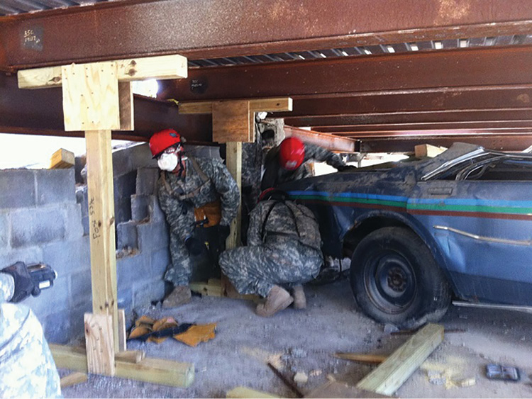
(1) Military responders practice installing prebuilt spot shores in a parking garage. (Photo by Jeremy Rifflard.)
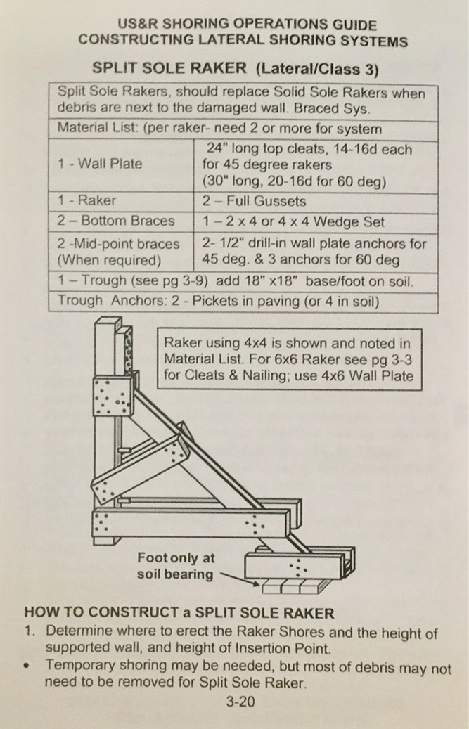
(2) Instructions from the Shoring Operations Guide for constructing lateral shoring systems.(Photo by Jeremy Rifflard.)
If your team does not have pneumatic shores available, wood shores are a good alternative. Wood shores require fairly precise measurements, but constructing them can be time consuming, so set up a cut station. This station would include saws, saw blades, electrical cords, generators, hammers, nails, and lumber. Give the cut team a plan of which shore needs to be constructed. The team may need to cut certain angles on the lumber, depending on what shore is being constructed. Wooden wedges may also need to be cut. Wedges are used to pressurize a complete lumber shoring system; they are placed under the posts that need pressure, or they can take up gaps between a shore and the structure.
RELATED
Simple Technique for Constructing Shores for Sloped Floors
Wood Shoring Systems: How Do They Perform?
INTERIOR VERTICAL SHORE, STEP BY STEP
Constructing shores from scratch may take up to one hour. Preassembling certain parts of a shore may reduce the overall time. According to Fort Lauderdale (FL) Technical Rescue Team Battalion Chief David Carter, his team has prebuilt header and sole plates for two post vertical and double-T shores. His team can take a shore, a battery reciprocating saw, and some nails and install a double-T shore quickly. Because the header and sole plate are prebuilt, the team can bypass the delay of setting up a cut station. If the posts are long, the team can trim with a battery circular saw on site. This cuts in half the time it takes to stabilize a building.
Prebuilt Split Sole Raker Shores
Split sole rakers are adaptable to level and solid surfaces or can be installed on uneven soil. They will also stabilize a wall that has a small debris field pressing against it. For these reasons, we prefer the split sole raker shore over other raker shores. The major components of the split sole raker are the wall plate, the raker, the trough, the anchor, and the braces. You can assemble many split sole parts before they are needed, while wall plates and troughs can be fully assembled. You can also ready wall plates with a 24-inch wall cleat that is nailed to the top of the wall plate. The cleat is attached with 14 nails in the pattern that is noted in the Shoring Operations Guide. This is the standard configuration for a wall plate that receives a 45° raker shore. The length of the wall plate can be up to 16 feet (if your apparatus can handle that length), but if you need a shorter length, cut it down on scene.
The wall plate can have a ½-inch hole drilled every four feet. These holes can accept pins or rebar to secure the wall plate to the structure. When a debris field is present on a wall that you need to stabilize, simply cut the wall plate to a length that will be higher than the debris.
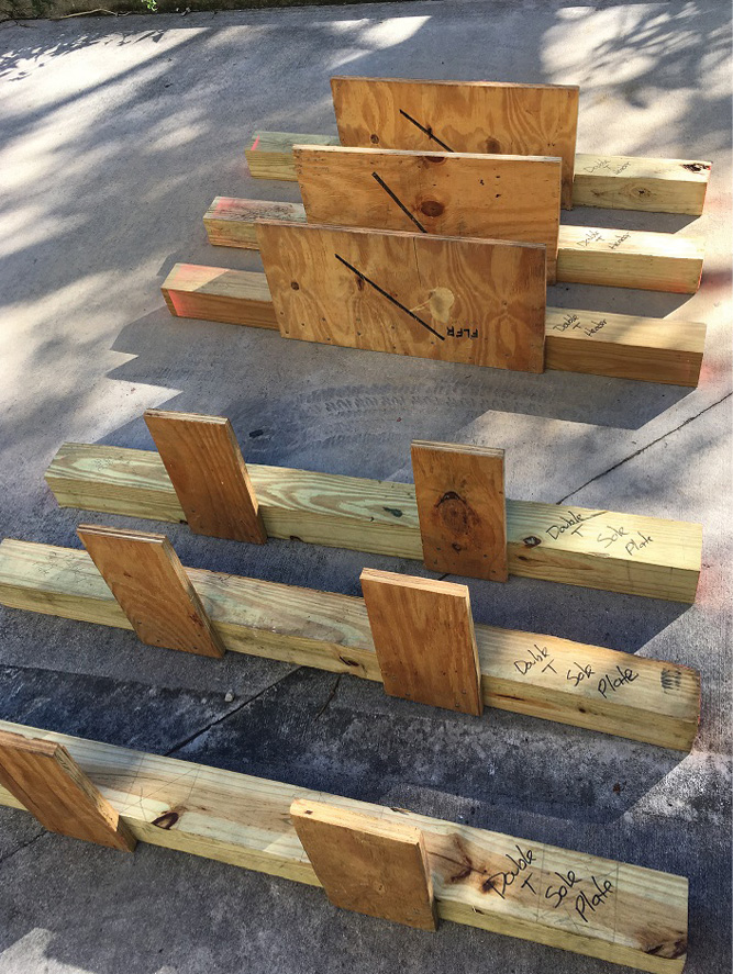
(3,4) The Fort Lauderdale (FL) Technical Rescue Team prebuilt this header and sole plate for vertical shores. (Photos by William White.)
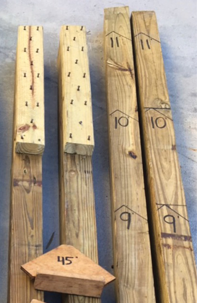
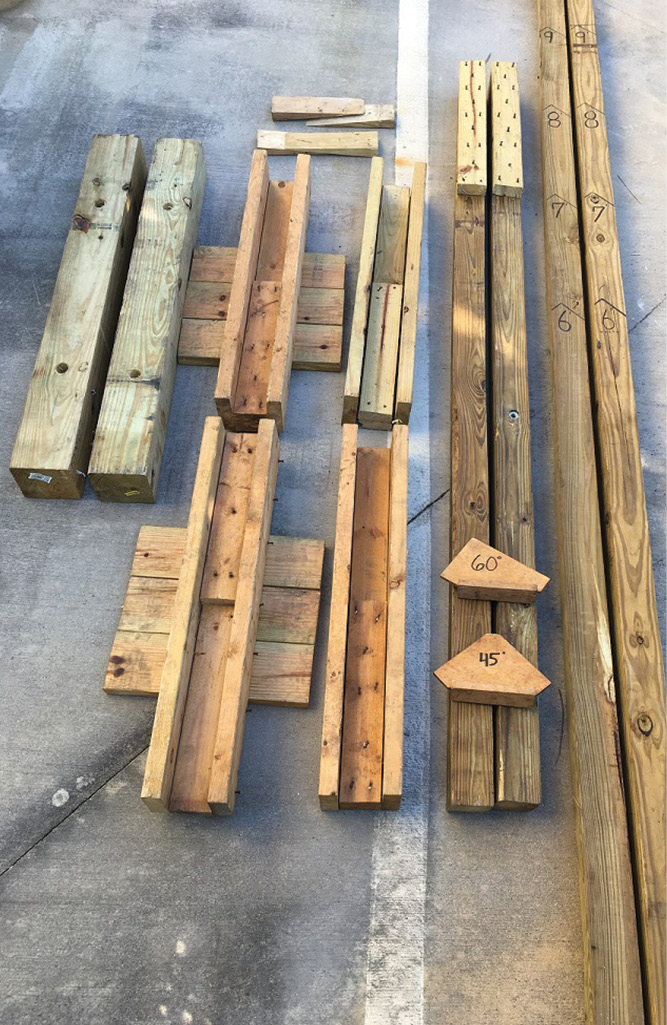
(5) These raker shores are marked every 17 inches for varying insertion points. (Photo by William White.)
The length of lumber for the raker is determined by a formula. In essence, the raker lumber represents the “long” side of a right triangle. The first piece of information you need to know is the connection height where the raker merges into the wall plate, known as the “insertion point.” This should occur at or just below the second floor or roof joists. The raker’s length will be longer than the insertion point height. For every foot of rise to the insertion point, the 45° raker lumber will be 17 inches in length. Therefore, when you measure and mark the length of the raker, do not measure every 12 inches—measure every 17 inches.
To reduce the construction time on scene, cut the raker at both ends at 45° with a 1½-inch return cut. You can mark the raker lumber for shorter lengths and then cut on site if it needs to be shorter. Calculating the angle for 30°, 45°, and 60° cuts can be challenging when this skill is not practiced regularly. Templates can make marking the angles easier. According to Fort Lauderdale (FL) Technical Rescue Captain Bill White, the team uses two templates to get angles on the end of lumber rapidly. One template has a 45° cut and a return cut on each end. The second template has a 30° angle on one end and a 60° angle on the opposite end. White’s team can trace the template on one end of the lumber and then slide it to the opposite end to draw the angles. Having part of the raker system prebuilt and the raker lumber marked for cutting takes a lot of thinking out of the equation on those 3 a.m. responses.
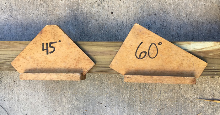
(6) Templates make the task of cutting raker angles much easier. (Photo by William White.)
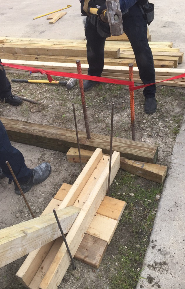
(7) The split sole raker is supported in a prebuilt trough. (Photo by Jeremy Rifflard.)
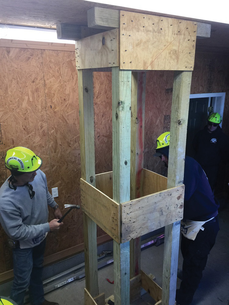
(8) Murray (KY) Fire Department firefighters install and lace together two prebuilt double-T shores. (Photo by Jeremy Rifflard.)
The two troughs for a pair of split sole rakers can be preconstructed. Each trough consist of a two-foot × four-foot and two-inch × six-inch lumber that is assembled in a manner that is 36 inches in length with an 18-inch cleat on one end of the trough as depicted in the Shoring Operations Guide. Three small 18-inch pieces of lumber are nailed to the underside of the trough for use on soil. They can easily be removed for split sole raker shores that are installed on level concrete.
Prebuilt Double-T Post Vertical Shores
Having two prebuilt double-T shores will take up an area of about 12 inches wide by three feet high for the length of the posts. In comparison, the uncut lumber will take up about six inches in width and two feet in height. There will be a loss of critical storage space when the shore is prebuilt. A best practice would be to tightly stack raw lumber in your transport trailer with the prebuilt shore sections on top of it.
To preassemble a double-T shore, cut a 36-inch header on two posts with the longest length that you can transport. Next, cut a 36-inch sole plate. Nail the double gusset on one side of the header with the nail pattern as shown in the Shoring Operations Guide. This provides a surface to “toenail” the posts to the header. On scene, rescuers will nail in place the second double gusset. To easily identify the shore components, label the lumber “two post vertical header” or “double-T sole plate” with a marker. The components can also be color coded. For instance, you can spray paint the ends of the raker shore sections orange and the double-T shores components vibrant green. You can nail half gussets six inches from each end of the 36-inch sole plate. If space is not an issue, you can build the entire double-T shore to the maximum 11-foot height, which includes the posts secured to the header and the double gussets nailed to the header, the posts, and the midpoint double gusset. If the area you are supporting is shorter than the length of this shore, trim the posts on the sole end. This is a very efficient technique.
Not all wood shores can be prebuilt, and there are also limitations on how much of a shore can be prebuilt. Storage of prebuilt shores can become an issue if you have limited space. Having partially constructed the significant parts of a split sole raker or a double-T shore can greatly reduce the amount of time that you spend on construction. Time is of the essence when it comes to protecting the patient and yourself, and prebuilt shores create a safe zone in a quicker, more efficient manner. Prepare before the incident occurs.
Reference
U.S. Army Corps of Engineers. Shoring Operations Guide. (2016). Retrieved from http://disasterengineer.org/LinkClick.aspx?fileticket=X6dPKr93U6E%3d&tabid=57&mid=394.
JEREMY RIFFLARD is an 18-year Florida firefighter and a captain with the Fort Lauderdale (FL) Fire Department. He is also a rescue squad officer for the Federal Emergency Management Agency Urban Search and Rescue team FL-TF2. Rifflard’s most recent task force deployments were to the Haitian Earthquake and Hurricane Ike. He is also the lead instructor of the Structural Collapse Technician programs for Coral Springs (FL) Regional Institute of Public Safety. For the past 15 years, he has been an instructor and subject matter expert for Military Urban Search and Rescue exercises through ATEC Incorporated in Jupiter, Florida.
WILLIAM WHITE is a 20-year member of the Fort Lauderdale (FL) Fire Department, where he has been a captain of the Technical Rescue Team for the past 13 years. White is also a technical rescue instructor at Coral Springs (FL) Regional Institute of Public Safety and a rescue specialist for USAR FL-TF2. For the past nine years, he has been a subject matter expert for the military search and rescue program through L2 Defense.

