
By Bill Gustin
Fire and building codes can be very dry information for fire suppression personnel who would rather focus on firefighting tactics. Codes and standards, such as those published by the National Fire Protection Association (NFPA), however, have an enormous effect on fire operations and can significantly influence firefighting tactics.
Scenario 1
A fire breaks out in apartment 1503 in a 23-story waterfront condominium. This is high-end real estate; each luxury unit measures at least 1,200 square feet. First-arriving companies observe light smoke from the balcony. Firefighters, equipped with forcible entry tools and 200 feet of 1¾-inch hose, check the fire alarm annunciator panel to verify the fire’s location, the 15th floor, and recall the elevators to the lobby by placing them in Phase I firefighter service. When the elevators arrive in the lobby, members place one of them in Phase 2 operation and ascend to the 13th floor, two floors below the reported fire floor.
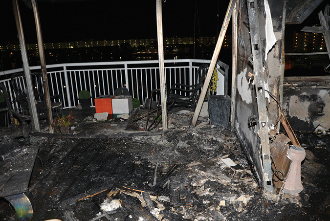
(1) Firefighters took a beating and risked being burned when fighting a fire in this large waterfront condominium unit with a 1¾- inch hoseline. (Photo by Ricardo Stephens.)
Familiarizing themselves with the floor below the fire, they find apartment 1403, directly below the fire apartment, to be about 50 feet from the East stairwell. Counting doors, they determine that the fire apartment will be the third door on the right.
Two engine companies team up to connect their 1¾-inch hoseline, charge it, and advance to the fire floor. The door to the fire apartment is closed, but smoke under pressure is pushing from around the door, filling the hallway with smoke. When the nozzle reaches the apartment door, the firefighters pull 50 feet of hose to the apartment door in a “U” configuration so that they have sufficient hose to reach every area in the fire compartment. So far, everything is going right, just the way they had trained. Although these companies train and are proficient in deploying 2½-inch hose from standpipes, they never experienced a need for it. But, this fire is going to be different.
These are young, aggressive, and physically fit firefighters, but their high-rise firefighting experience is limited to modern, fully sprinklered buildings with state-of-the-art fire protection. They are about to face an entirely different animal.
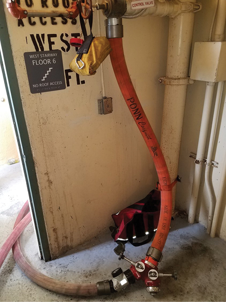
(2) A “pigtail,” a short section of three-inch hose, connected to a wye supplying a 2½-inch hoseline. Using the wye to flow two lines from one outlet may not be possible because it will exceed 250 gpm, the minimum flow required by NFPA 14 for standpipe hose outlets. (Photo by Eric Goodman.)
This building was constructed in 1971, years before they were born. When this building received its certificate of occupancy, sprinklers were not required, and a single six-inch-diameter, dead-end water main was permitted to supply water for both domestic use and a 500-gallon-per-minute (gpm) fire pump that operates at a churn (maximum) pressure of 150 pounds per square inch (psi). Since this building was constructed before 1993, NFPA 14, Standard for the Installation of Standpipe and Hose Systems, required a minimum hose outlet pressure of 65 psi at a flow of 500 gpm. There’s no argument that the outlet pressure will probably be higher when the system is flowing less than 500 gpm, but it is critical to consider the age and condition of the building’s standpipe system and its appalling water supply.
The target flow for this department’s 1¾-inch hoseline is 185 gpm; that requires a standpipe hose outlet pressure of 105 psi to overcome 50 psi friction loss in 200 feet of hose, achieve 50 psi nozzle pressure on a 15⁄16-inch smooth bore tip, and an additional 5 psi to compensate for the elevation loss from connecting to an outlet on the floor below the fire.
Now, let’s calculate the water flow necessary to suppress a fire in a fully involved 1,200 square-foot apartment by using the National Fire Academy’s fire flow formula: 1,200 square feet ÷ 3 = 400 gpm. When these firefighters forced the door to the fire apartment, it opened to a blast furnace. With courage and tenacity, they took a tremendous beating fighting a fire that was beyond the suppression capability of their 1¾-inch hoseline.
After a lengthy and punishing fight, they extinguished the fire, but they were very lucky. Had there been the slightest wind blowing in the windows, they could have been terribly burned (photo 1).
Use of Wyes for Standpipe Operations
Many fire departments, including mine, require the use of a wye for standpipe operations (photo 2). The purpose of a wye is to supply a second hoseline from one standpipe outlet. Fire officers who intend to use a wye to supply two hoselines from a single hose outlet may want to rethink that tactic when they consider the flow requirements in NFPA 14. The standard requires a minimum flow of 250 gpm per hose outlet, for a total of 500 gpm from two outlets per standpipe. There are, of course, standpipe outlets that will flow much more than 250 gpm, sufficient to supply two hoselines or a portable master stream device; but this cannot be depended on unless it has been confirmed by a flow test.1 When charging a second hoseline from a standpipe, it is critical to flow the first hose and closely monitor its pressure on its inline gauge to ensure that the second hoseline does not “steal” water from the first. Anticipate a drop in pressure in the first hoseline when the second one is charged. Additionally, it is very important to S-L-O-W-L-Y charge the second line to observe and compensate for a loss of pressure in the first hoseline.
Understanding Pressure-Reducing Valves
My first encounter with pressure reducing valves (PRVs) was several years ago when they were installed in government-subsidized multiple dwellings under construction in my company’s district. I knew of the tragedy involving PRVs at One Meridian Plaza in Philadelphia in 19912 but had no firsthand experience with them. Before the buildings were occupied, the fire suppression system contractor gave my company permission to stretch and flow hoselines from the building’s standpipes. The drill site was a 10-story building. Signs posted at fire department connections (FDCs) clearly indicated a system demand pressure of 205 psi, which seemed a bit high to us. Confident in our knowledge of standpipes, we ignored the sign posted at the FDCs and calculated the pressure to pump the FDC the way we always did: Multiply the number of floors by 5 psi elevation loss per floor, and add 100 psi for the nozzle pressure and friction loss in the hoseline.
We asked the contractor to turn off the building’s fire pump and told him of our intention of pumping into an FDC at our calculated pressure 150 psi. He told us to go right ahead but that he doubted that we would flow an adequate stream pumping the FDC below the posted demand pressure. The contractor was right, and I was embarrassed. When we connected and flowed a hoseline from a first-floor outlet, the stream looked like it came from a garden hose. We had a lot to learn, but we were fortunate to have met someone who was willing to teach us.
The suppression contractor explained that for the building to receive a certificate of occupancy, it must pass a flow test flowing 500 gpm at 100 psi from the two most hydraulically remote hose outlets of the most hydraulically remote standpipe and 250 gpm at 100 psi from the second standpipe’s roof outlet. Another factor to consider was the friction loss in the system: Flowing a total of 750 gpm, which had to be calculated into the system’s demand pressure, and elbows in the system’s piping add considerably more friction loss. These government public housing buildings had combination sprinkler/standpipe systems designed to supply sprinklers at a discharge density of 0.1 gpm per square foot, required by NFPA 13, Standard for the Installation of Sprinkler Systems.
Water supply to sprinklers was another factor in calculating system pressure. We now had a better understanding of why the demand pressure posted at the FDCs was so high in our estimation, but we were still puzzled about why we had such a poor stream from a first-floor outlet when we pumped the system at 150 psi, 55 psi below its demand pressure.
The suppression system contractor explained that NFPA 14 limits the maximum pressure from hose outlets to 175 psi and, since the system on lower floors was well above that pressure, devices had to be installed to keep outlet pressure from exceeding 175 psi. As a result, pressure-reducing hose outlet valves were installed on the lower floors of this building. These buildings had PRVs that were set at the factory to keep both static and residual/flow hose outlet pressures from exceeding 175 psi. Additionally, since this was a combination sprinkler/standpipe system, factory-set pressure-reducing floor isolation valves were installed to keep the pressure to sprinkler heads from exceeding 165 psi.
We learned how important it was for PRVs to be installed on the proper floor within a certain range of pressures. Because of pressure loss caused by elevation, PRVs installed on lower floors will have more pressure-reducing effect than those on upper floors. In these buildings, conventional hose valve outlets were installed on upper floors because elevation reduced the valves’ inlet pressure below 176 psi. We learned a valuable lesson: If the building’s fire pump or fire apparatus pumping an FDC supplies the system below its design demand pressure, the PRVs will not operate as they were designed. Similarly, installing a PRV intended for a high pressure on a lower floor on an upper floor with lower system pressure by mistake will have the same effect: The valve will not flow water as it was designed. PRV standpipe hose outlets and sprinkler floor isolation valves must be flow- and pressure-tested in accordance with NFPA 25, Standard for the Inspection, Testing, and Maintenance of Water-Based Fire Protection Systems. Manufacturers of PRVs assume no liability for defective equipment if there is no record of their being tested in accordance with NFPA 25.3
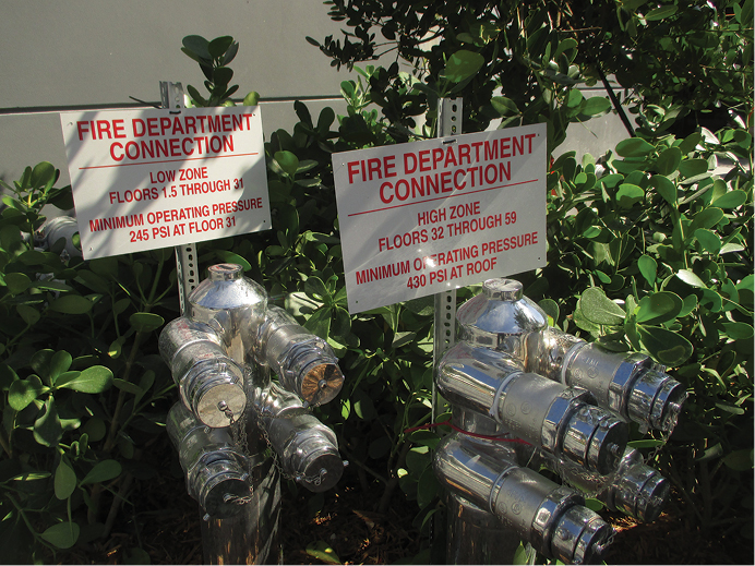
(3) Demand pressures posted at FDCs for a system divided into two zones: The low zone, which reaches the 31st floor, requires a pressure of 241 psi; the high zone, which begins on the 32nd floor, requires 430 psi. (Photos 3-4 by Blas Bravo.)
Understanding Zoned Standpipe Systems
Consider the elevation or head pressure at the base of a standpipe that reaches the 20th floor. For the sake of simplification, let’s assume that it is 200 feet tall. One of the first hydraulic principles beginning firefighters learn is that a column of water one foot high will exert 0.434 psi; hence, the pressure at the base of a 200-foot standpipe is calculated by multiplying 200 by 0.434, which equals 86.8 psi. It doesn’t matter whether this 200-foot standpipe reaches from the 1st floor to the 20th floor or from the 21st floor to the 41st floor; the head pressure will be the same, 86.8 psi. This is the concept behind installing standpipe systems in zones at different levels in some tall buildings.
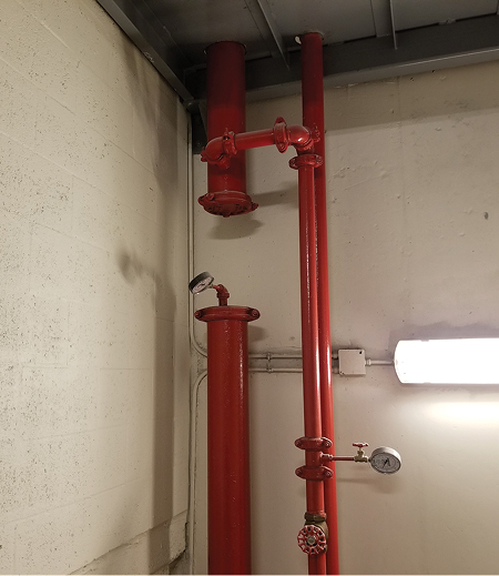
(4) The standpipe system in this 46-story office building is divided into two zones. The low zone terminates at the 23rd floor, and the high zone begins on the 24th floor and terminates at the roof.
In Photo 3, this 59-story building has a standpipe system divided into two zones: the low zone, which reaches the 31st floor, requires a pressure of 241 psi; the high zone, which begins at the 32nd floor, requires 430 psi. Later, this article examines why apparatus supplying an FDC must compete with a building’s fire pumps to become the source of water pressurizing a system.
In photo 4, the standpipe system of this 46-story office building is divided into two zones; the low zone terminates at the 23rd floor, and the high zone begins at the 24th floor and terminates at the roof.
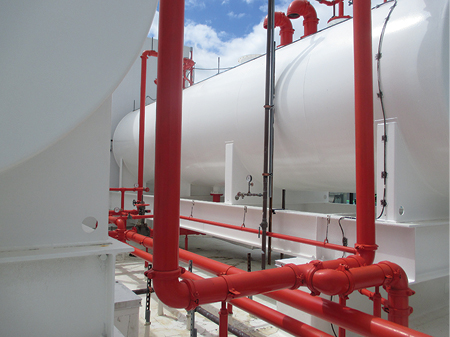
(5) Two 12,000-gallon tanks supply water to the high-zone fire pump. (Photos 5-6 by Blas Bravo.)
In photo 5, two 12,000-gallon tanks supply water to the high-zone fire pump on the roof (photo 6), which pumps downward to pressurize the system from the roof to the 24th floor.
(6) The test connection for the high-zone fire pump is on the roof. Each outlet flows 250 gpm; hence, the pump has a capacity of 1,000 gpm.
It is not uncommon to find buildings that have two standpipe zones with the pumps supplying both zones on the same level.
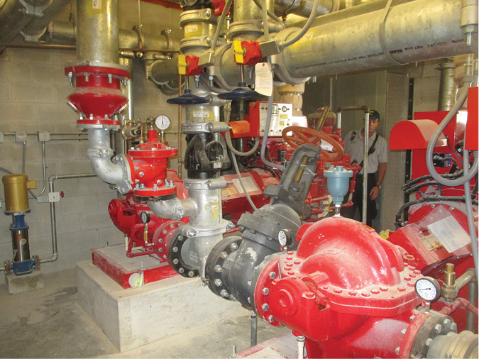
(7) Two diesel-driven fire pumps operate in a series to supply a two-zone combination sprinkler/standpipe system. The low-zone pump supplies the low zone and discharges into the intake of the high-zone pump, essentially doubling the pressure developed by the high-zone pump. (Photos 7-9 by Eric Goodman.)
In photo 7, two diesel fire pumps operate in series, similar to how two fire department engines would operate in a tandem pumping operation. The low-zone pump supplies the low zone and discharges into the intake of the high-zone pump, essentially doubling its pressure for the high zone.
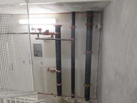
(8) Three risers at the ninth floor landing. (Left) the low-zone riser terminates, (center) the express drain riser, (right) the high-zone riser is devoid of outlets. The outlets for the high zone begin at the 10th floor.
In photo 8, notice that there are three risers at a ninth-floor landing of this 25-story building. On the left, the low-zone riser terminates. This riser supplies sprinklers and hose outlets from the first to the ninth floors. Notice the one-inch drain pipe downstream of the floor isolation valve connected to the center, express drain riser. The high-zone riser, on the right, is devoid of outlets; outlets for the high zone begin at the 10th floor. There are just two risers from the 10th to the 25th floors, the high-zone and the express drain riser (photo 9).
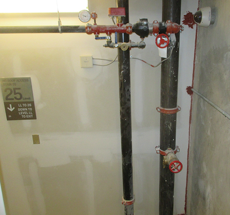
(9) There are just two risers above the ninth floor, the high-zone riser and the express drain riser.
Learning HVAC and Smoke-Control Systems
A disgruntled woman doused her husband’s bed with lighter fluid and set it on fire while he was sleeping in it. The couple, who apparently were having marital issues, lived on the 23rd floor of a 25-story luxury high-rise condominium building. After the husband’s rude awakening, he fled, leaving the door to the public hallway open. Sprinklers kept the fire, involving a king-size, foam-rubber mattress, from spreading but could not keep dense smoke from filling the 23rd floor. Firefighters with a hoseline finished extinguishing the fire, shut off the sprinklers, and opened sliding glass doors to ventilate. Within minutes, the first-floor lobby filled with smoke. What happened?
This was a hot summer day; the outside temperature was in the mid-90s, whereas the temperature in the air-conditioned building was in the low 70s. Conditions were perfect for reverse stack effect: Warm, moist air entering the apartment rapidly cooled, became less buoyant, and sank down the stairwells and elevator shafts. Firefighters unintentionally enhanced the reverse stack effect by chocking open doors in the lobby and at the base of the stairwells. This reduced the pressure created by the air-conditioning system in the lobby and created a flow path of smoke to exterior openings on the first floor.
It’s muscle memory. Beginning in recruit training, firefighters are trained to chock open every door they pass through. This not only enhances the effect of reverse stack effect, but it also reduces the effectiveness of a building’s smoke-control system. Modern commercial and residential high-rise buildings have pressurized stairwells; on activation from the fire alarm system, powerful fans, typically on the roof of the building, pressurize the stairwells to keep smoke from migrating into them. Firefighters reduce the effect of stairwell pressurization when they chock open stairwell doors. Some systems are designed to overcome the pressure loss when firefighters must open stairwell doors to advance a hoseline but cannot keep up with the pressure lost when firefighters chock open roof bulkhead and ground-floor stairwell doors that open directly to the outside. Instead of chocking doors open, firefighters should keep doors that will relock on closing ajar by using rubber search/latch straps, clamps, or a device that hooks over a hinge.
Modern office buildings typically have no windows that can be opened for ventilation and are dependent on a smoke-control system to exhaust smoke and keep it from spreading beyond the fire floor. Smoke-control systems in large buildings consist of an elaborate and complicated array of fans, ductwork, and dampers. Unless it is having an adverse effect, it is recommended that firefighters let them operate in the automatic mode. It is important for fire officers to gain a basic understanding of these systems during prefire planning by consulting with the building’s engineering staff.
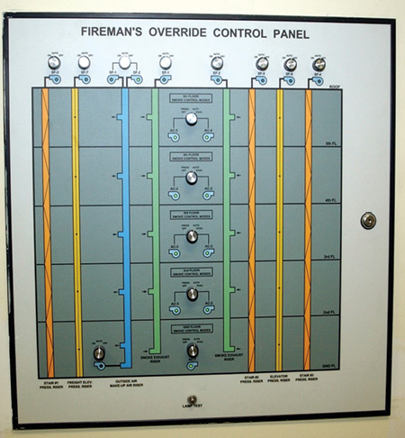
(10) A photo of a schematic of a smoke-control system on the control panel. (Photos 10-11 by Eric Goodman.)
Although an in-depth examination of smoke-control systems is beyond the scope of this article, the schematic of a smoke-control system on the control panel in photo 10 illustrates the basic components and functions of a smoke-control system in a five-story office building. Large fans on the roof (photo 11) are connected to ducts running the height of the building.
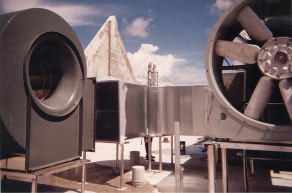
(11) Large fans on the roof exhaust smoke from the fire floor and pressurize stairwells, elevator shafts, and floors above and below the fire floor.
Say a fire is detected on the third floor. The alarm system will turn on the fans and open and close dampers to exhaust smoke from the third floor and pressurize the second and fourth floors and the stairwells and elevator shafts to keep them clear.
Photo 12 was taken on a floor of a commercial high-rise building before it was occupied by offices. This building is of center core construction, which is a common design for commercial high-rises. It has an air-handler in the core on each floor to heat or cool the air. Although 80 percent of the air is recirculated back to the air-handler to be reheated or cooled, codes require that the recirculated air must be mixed with 20 percent of fresh, outside air, which is supplied by a central supply duct. Notice that a supply air duct is extending from the core. This duct will branch out to offices depending on the floor plan specified by the tenant. There is, however, no return air ductwork, which is typical for this type of building. When the ceiling is installed, air will return in the plenum or space between the ceiling and the floor above back to the air-handler in the core. The plenum is also used by the building’s elaborate smoke-control system (photo 13) to exhaust smoke from the fire floor and pressurize vertical shafts and two floors above and two floors below the fire floor.
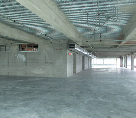
(12) A floor of a commercial high-rise building before it is occupied by offices. The supply heating, ventilation, and air-conditioning duct extends from an air handler in the core; there is no return air ductwork. When the ceiling is installed, air will return in the plenum space between the ceiling and the floor above to the air handler. (Photo by Blas Bravo.)
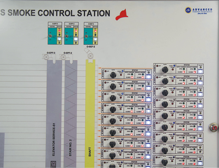
(13) A portion of a control panel for an elaborate smoke-control system. The switches, which control dampers and fans, have four selections: Off, Automatic Mode, Pressurize, and Purge. (Photo by Ricardo Stephens.)
This is just a cursory overview of how a building’s heating, ventilation, and air-conditioning (HVAC) and smoke-control system operate, but it begs the question: Should fire officers order the HVAC system to be shut down in a fire? As a young officer and student of the fire service, I was taught to shut down the HVAC because it will feed fresh air to the fire and circulate smoke to areas far from the fire. I have posed this question to several experienced building engineers and a veteran building department mechanical inspector. They all advise that we do not shut down the building’s HVAC. They explained that when a HVAC system is shut down, pressure in the central air-supply ducts is lost and, consequently, they can fill with smoke that can then spread to other floors. Additionally, they advise that a modern high-rise building has several safeguards in the HVAC such as motor-operated dampers and fan switches activated by smoke detectors in the ductwork to reduce or eliminate the circulation of smoke. The most sensible stance to take is to decide whether to shut down a HVAC system on a building-by-building basis. The decision should be made during prefire planning in consultation with a building engineer who has intimate knowledge of the system. Knowledge of a building’s HVAC system is vital prefire intelligence for an officer in command of a high-rise fire.
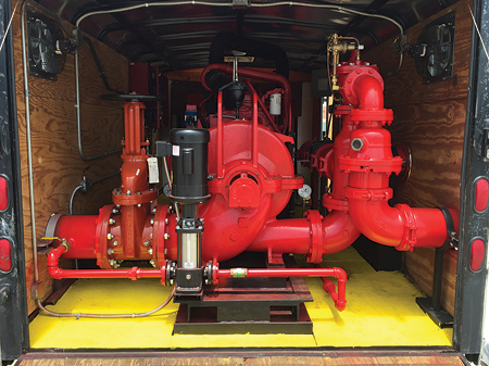
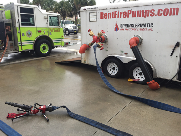
(14) This fire pump trailer contains a diesel-driven fire pump, a jockey pump, and controllers for both pumps. (Photo by Mike Posner.)
Alliance with Sprinklermatic
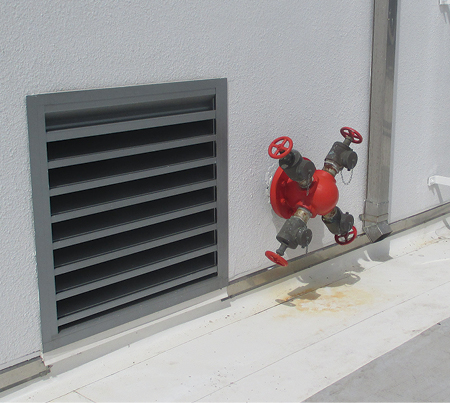
The relationship between Miami-Dade Fire/Rescue and area fire suppression system contractors has been nothing but positive. I believe that this is mostly because of the mutual respect among firefighters, sprinkler fitters, and fire pump technicians. In a sense, we are a team working for the same goal. We respect and appreciate what each other does to protect the public from fire. We have never had a contractor deny our request to drill with its standpipe systems while a building was under construction or to borrow valves and other system components for our Officer Development Program. An outstanding example of this cooperation occurred last May when Sprinklermatic, a high-rise building suppression system contractor, agreed to connect one of its fire pump trailers to the tower at Miami-Dade’s training facility and team up with Miami-Dade instructors to teach classes for fire suppression and fire prevention personnel from South Florida fire departments. The pump trailer takes the place of a building’s fire pump when it is out of service for repairs. The trailers are equipped with a diesel-driven fire pump, an electric jockey pump, controllers for both pumps, and a diesel fuel tank (photo 14). In photos 15-16, Sprinklermatic pipe fitters connected the pump’s intake piping directly to the tower’s back flow prevention device and plumbed the pump’s discharge piping and FDC into the tower’s standpipe system. It was a unique opportunity for learning because the pump trailer, the fire apparatus supplying the FDC, and the master stream devices flowing water were in proximity. Intake and discharge gauges for the pump trailer and the engine pumping the FDC could be readily observed because they were just a few steps apart (photo 17).
This was also an opportunity for the contractor to get the word out to firefighters not to close the PRV or outside stem and yoke (OS&Y) valves isolating a backflow prevention device without first shutting down a building’s fire pump. Fire pump technicians explained that closing those valves shuts off the municipal water supply to the intake of the fire pump, resulting in a loss of water to cool the pump and its diesel driver. The technicians explained that, unlike a motor vehicle, a diesel engine driving a pump does not have a radiator; it requires a continuous flow of water to keep it cool. They pointed out things that a firefighter assigned to a fire pump room should look for to ensure that the pump is running; the proper valves are open; and, equally as important, the fire pump will continue to run. The technicians explained that when a diesel fire pump is running, firefighters should see a continuous stream of cooling water from the diesel engine discharging into a floor drain in the fire pump room (photo 18) and they should also see a small amount of water dripping from its packings, which is necessary to keep the pump’s impeller shaft cool and lubricated.
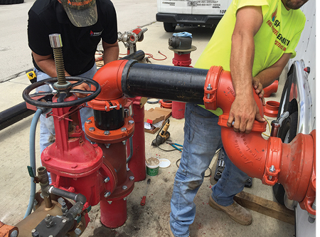
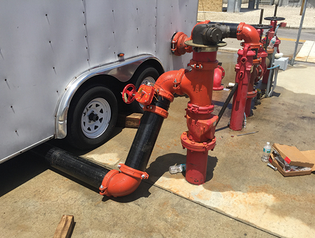
(15-16) Sprinklermatic pipe fitters connect the pump’s intake to Miami Dade’s training facility’s water main and plumb the pump’s discharge piping directly to the training tower’s standpipe system. (Photos by Mike Posner.)
The pump technician demonstrated the function of the jockey pump by cracking open a valve in a small water line to its controller. This resulted in a slight drop in system pressure, which caused the jockey pump to run until the pressure was restored. He then demonstrated the function of the fire pump’s controller by flowing sufficient water to reduce system pressure to the pressure programmed into the controller, automatically starting the diesel engine driving the pump. Students had an opportunity to observe how intake piping from the FDC is plumbed into the discharge piping of the fire pump and to learn the function of check valves in piping for the FDC and the fire pump’s discharge piping. As mentioned earlier, fire department pumpers supplying FDCs must compete with a building’s fire pump to become the source of water supplying a system.
Water Supply and the Fire Suppression System
There is a common misunderstanding in the fire service that a fire department pumper supplying an FDC is augmenting or supplementing the discharge of the building’s fire pump. This is not true because there can be only one source of water supplying a fire suppression system—either the building’s fire pump or a fire department, whichever is pumping the highest pressure. We demonstrated this by deliberately setting the pressure of the engine pumping the FDC below the pressure developed by the diesel fire pump. We placed a demand on the diesel pump by supplying two 400-gpm portable master stream devices from the training tower’s wall hydrant. As intended, the pressure developed by the fire department pumper was insufficient to open check valves in the piping to the FDC that were held closed by the higher pressure developed by the trailer’s diesel fire pump; hence, the fire department pumper was not flowing any water.
(17) This portable master stream device is connected to the pump trailer’s test connection. The intake and discharge gauges for the pump trailer and the engine pumping the FDC could be readily observed because they were close. (Photo by Mike Posner.)
This was further demonstrated by closing the discharge valves to the three-inch hoselines connected to the FDC and observing pressures on the pump panel gauges. Predictably, all pressure readings remained the same. Since the apparatus pump was not flowing any water, it would rapidly overheat without flowing some water from a drain or a hoseline. We then raised the pressure of the engine connected to the FDC above the pressure developed by the trailer’s pump and observed a drop in the engine’s intake (residual pressure). The fire department engine now became the source of water, pushing open check valves in the FDC piping and forcing the check valve in the pump trailer’s discharge piping to close. Just as fire apparatus pumps must flow water to keep them from overheating, building fire pumps must do the same. To flow water when a pump is “at churn,” electric pumps are equipped with casing relief valves; whereas diesel-driven pumps continuously flow water from their discharge through a heat exchanger of the engine’s cooling system. Water discharging from an electric pump’s casing relief valve or a diesel engine’s heat exchanger should be observed running into a floor drain in a fire pump room. Sprinklermatic connected a miniature sprinkler riser to the training tower’s wall hydrant to demonstrate the flow from a variety of sprinkler heads and how to properly close a floor isolation valve and open the sprinkler’s one-inch drain line. There were hands-on work stations for adjusting field-adjustable PRVs, troubleshooting FDCs, and pumping into a first-floor standpipe outlet if the FDCs have been damaged or vandalized.
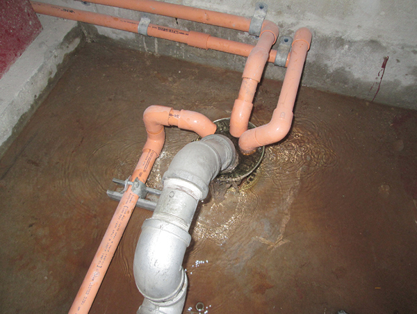
(18) When a diesel fire pump is running, firefighters should see a continuous stream of cooling water discharging into a floor drain in the fire pump room. (Photo by Ricardo Stephens.)
Students learned, however, that supplying a standpipe by connecting a hoseline from a fire department pumper to a first-floor outlet is not possible if it is a PRV. This was demonstrated by connecting a 2½-inch hoseline with a double female adapter to a PRV outlet and charging the line. The PRV acted as a check valve and would not flow water. In this situation, the only alternative would be to pressurize the system by connecting hoselines from a fire department pumper to the fire pump’s test connection and opening its valve inside the pump room.
“Sprinklermatic University”
Sprinklermatic has built a facility for training firefighters, fire inspectors, and the fire sprinkler industry. “Sprinklermatic University” conducts classes approved by the Florida Bureau of Firefighter Training and Standards for fire department personnel’s receiving continuing education units (CEUs) required to maintain their Florida Fire Service certifications. This a unique facility for hands-on training because each system flows water supplied by a diesel fire pump and every valve is operable.
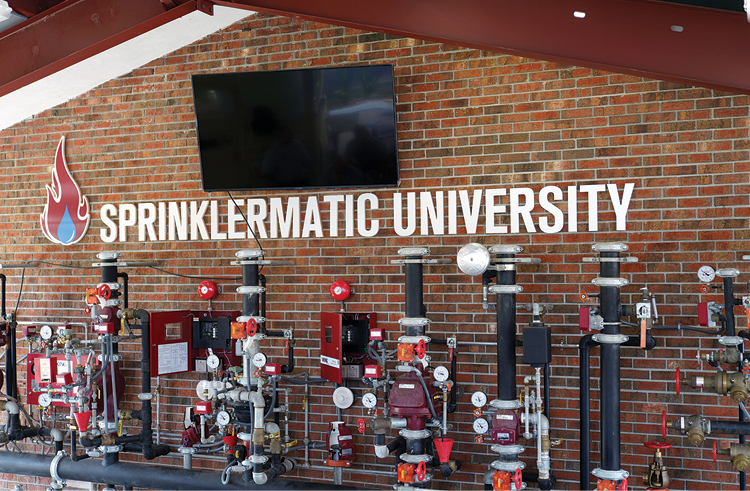
(19) An array of systems and valves at Sprinklermatic University. (Right to left) a 13-D system; a 13-R system; an assortment of pressure-reducing and conventional hose outlets and floor isolation valves; a modern sprinkler riser with a flow switch and a two-inch drain line; an “old school” sprinkler riser with an alarm check valve, a retard chamber, and a water motor gong; a dry pipe valve and riser; a single-interlock preaction system; a double interlock preaction system; and a “Fire Cycle” sprinkler system. (Photo by Eric Goodman.)
Although a detailed description of the function and components of each system is not within the scope of this article, the array of systems in photo 19 increases in complexity (right to left) beginning with a 13-D residential one-inch black steel pipe riser. The array includes a two-inch riser 13-D system, a variety of functional and cutaway PRVs, an “old school” sprinkler system riser with an alarm check valve and water motor gong, a dry pipe valve, and single- and double-interlock preaction systems.
The most sophisticated system, the “Fire Cycle,” on the far left, can automatically control the flow to sprinklers without human intervention. When sprinklers extinguish a fire, heat detectors sense a reduction in temperature, and the system stops the flow of water. If the fire should rekindle, heat detectors, sensing a rise in temperature, will signal the system to again flow water. The facility’s fire pump also supplies an array of sprinkler heads that are controlled by electrical solenoid-actuated valves. With the flip of a switch, students can observe the operation of pendant and side wall heads for 13-R and 13-D residential sprinkler systems, flowing approximately 15 gpm and heads for commercial occupancies, which they can see flow considerably more water. Most impressive are early-suppression/fast-response sprinkler heads that can flow more than 150 gpm. ESFR sprinklers are supplied by large piping and operate at higher pressures than conventional sprinkler heads. ESFR heads are so effective that they can be installed overhead of storage racks without necessitating in-rack sprinklers, if the sprinkler system is engineered properly. Additional information on Sprinklermatic University, including several videos, is at www.sprinklermatic.net.
Fire suppression personnel must learn building systems. If you do not learn how to control systems, they may, at some point in your career, control you.
References
1. “Operating More Than One Hoseline from a Standpipe,” Bill Gustin, Fire Engineering, May 1, 2015.
2. “One Meridian Plaza Fire,” Harry Eisner with Bill Manning, Fire Engineering, August 1991, https://bit.ly/2HXX5lX.
3. “Testing Pressure-Reducing Valves,” Bill Gustin, Fire Engineering, January 24, 2014.
Bill Gustin is a 45-year veteran of the fire service and a captain with the Miami-Dade (FL) Fire/Rescue Department. He began his fire service career in the Chicago area and is a lead instructor in his department’s Officer Development Program. He teaches tactics and company officer training programs throughout North America. He is an advisory board member of Fire Engineering and FDIC International.

