The Gasoline Tank Truck: Design and Construction
HAZARDOUS MATERIALS

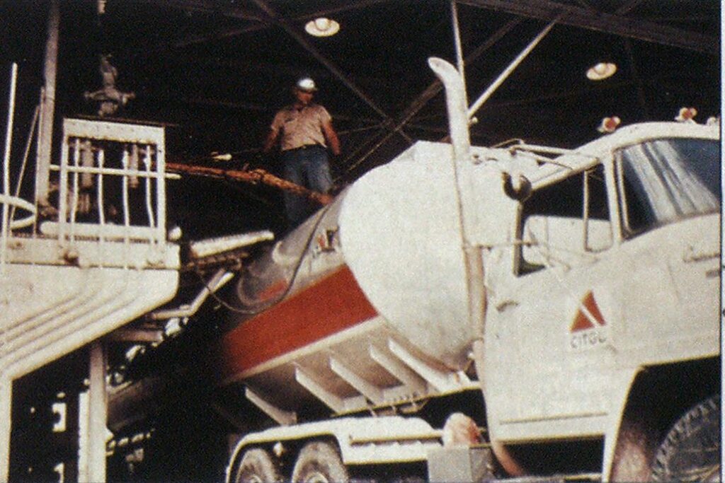
Photo by Citogo Petrleum Corp.
The first of two articles on one of the most common forms of hazardous material transport.
Flammable and combustible liquids are an integral part of our daily lives. Products such as gasoline, jet fuels, fuel oil, and kerosene are used to power vehicles in all modes of transportation, to heat our homes, and to produce energy for various industrial applications. A complex transportation network is required to move these products to the end user. At the heart of this transportation network is the MC-306 cargo tank truck or, more commonly, the gasoline tank truck.
In its July 1986 report to Congress entitled Transportation of Hazardous Materials, the Office of Technology Assessment reported that gasoline accounted for almost half of all hazardous materials transported by tank truck in the United States. More than 40,000 deliveries of gasoline are made to service stations daily, with the average delivery distance being only 28 miles. So regardless of location, every community faces the potential of a gasoline tank truck emergency.
MC-306 tank trucks are used to transport products that have vapor pressures of less than 3 pounds per square inch and that fall into one of three categories: flammable liquids (which emit a flammable vapor at less than 100° F); combustible liquids (which emit a flammable vapor at between 100° and 300° F); and Class B poisons, as designated by the U.S. Department of Transportation.
These tanks are commonly constructed of aluminum, although older steel and stainless steel tanks may be found. A third type of tank, made of fiberglass reinforced plastic (FRP), is now being tested in certain areas of the United States. The FRP tanks reportedly are more resistant to fire and impact and are less likely to roll over than the standard aluminum MC306 tank truck.
Unlike steel, aluminum-shell tank trucks will melt at temperatures as low as 1,200° F when impinged by fire at the vapor space above the level of the stored liquid. Boiling liquid, expanding vapor explosions aren’t a common hazard when dealing with aluminumshell tankers, because, although spectacular, gasoline tank truck fires often become open tank or “pit” fires after the aluminum shell melts down.
Unlike pressurized containers, MC-306 tank trucks are elliptical. They’re constructed of sheets of aluminum which are form-rolled, then welded along the seams. When tank ends and internal baffles are attached to the container or “barrel,” the tank becomes a structural unit. As a result, the tank’s integrity doesn’t depend on the chassis or trailer for support. In an emergency, greater attention should be directed toward the barrel than the framing to which it is attached.

Tank capacities range from 2,000 to approximately 9,500 gallons. Tandem tank trucks or “pups” of up to 5,000 gallons capacity each are common in the Western states. Federal and state vehicle weight limits—rather than volume restrictions—are the primary criteria for determining vehicle loads and capacities. To transport several products simultaneously, tank trucks are divided into compartments— usually four or five, but sometimes as many as eight. In general, the front and rear compartments are the largest. A minimum of 3% of each compartment must be left empty as a vapor space for product expansion.
Compartments are separated by disk-shaped bulkheads similar to the tank ends. Many newer tank trucks have double bulkheads between compartments to prevent fuel contamination and make cleaning the tank easier. On double compartment bulkheads, there will be small vents and drain plugs from both the top and bottom of the space between bulkheads. These are visible on the outside of the tank. If the bottom drain plug isn’t in place and product is leaking from the space, it usually indicates a leaking compartment bulkhead.
By the Numbers
The U.S. Department of Transportation lists five categories of cargo tank trucks:
- Nonpressure tank trucks— MC-302, MC-303, MC-305, and MC-306.
- Low-pressure chemical tank trucks—MC-304 and MC-307.
- Corrosive tank trucks—MC310, MC-311, and MC-312.
- High-pressure tank trucks— MC-330 and MC-331.
- Cryogenic tank trucks—MC338.
Don’t be confused by the variety of tank specification numbers. Each of the first four categories has been narrowed down, so that trucks in those categories being constructed since 1967 are built only to the MC306, MC-307, MC-312, and MC331 specifications. The MC-338 specification for cryogenic trucks was created in 1983.
Within each compartment are baffles that minimize product surges during transportation. They’re open in the center and at the “6 and 12 o’clock” positions. To make it easier to remove products from a tank involved in a rollover, some tank manufacturers and petroleum companies will place additional baffle openings at the 3 and 9 o’clock positions. Tank trucks so equipped are often identified by black dots painted on each tank end at the 3 and 9 o’clock positions.
There are several indications of the number of compartments and the capacity of each:
- Manufacturer’s specification plate. Each tank constructed to DOT specifications must have a certification plate, usually located at the right front of the tank. The plate provides the DOT container specification number (MC-306), date of manufacture and test, shell material, number of compartments and their capacity, and maximum product load.
- Number of dome covers. There will generally be one dome cover for each compartment. How-
- ever, there are “foolers”—two dome covers may be found on sdme tank trucks with large front and rear compartments. If in doubt, compare the number of bottom valves with the number of dome covers.
- Number of discharge outlets or control valves. Each compartment will have its own control valve. A compartment will either be piped to its own discharge outlet or be tied into a manifold. Because leaded and unleaded gasolines cannot be mixed, individual piping and discharge outlets are more common on gasoline tank trucks, while manifolds will be found on fuel oil tank trucks.
- Capacity markings painted along the overturn rail. When provided, these will often consist of three numbers per compartment painted on the side of the overturn rail, a rail that guards openings in case of a rollover. If the dome cover on a tank compartment is opened, a vertical rod intersected by three disks (known as “butterfly markers”) will be visible. These mark three levels of fullness—generally 100, 75, and 50 percent. The markings on the overturn rail correspond to these percentages and can be helpful in quickly assessing the capacity of a compartment.
MC-306 cargo tanks have the following safeguards:
- Internal safety valves. One is required for each compartment. The valve sits inside the compartment to protect it from mechanical damage. Within inches of the tank shell is a shear section of piping designed to break under mechanical stress. If a collision causes such stress at that point, the piping should fail at the shear point while the internal valve remains intact within the compartment, thereby minimizing product loss.
- Fusible links and nuts. These are found at various locations on cable-, air-, and hydraulic-actuated systems. In the event of a spill fire under or around the vehicle, the fusible link or nut will melt, releasing cable tension or pressure. The fusible links and nuts are required to actuate at temperatures not greater than 250° F. Again, the effectiveness of these safeguards often depends on preventive maintenance.
- Emergency remote control valves. These control valves, when actuated, automatically close all internal safety valves. They’re designed for use during product transfer operations should a spill or fire block personnel from reaching the discharge outlets and controls on the right side of the vehicle.
- Vacuum and relief valve protection. Both normal and emergency relief protection is required on all tank vehicles. Common relief devices include relief valves, fusible plugs, and pressure vents. These devices will usually be part of the dome cover assembly. They are designed to open into the vapor space of the container, and must be mounted to prevent any accumulation of water or ice from impairing their operation. In a rollover, pressure relief devices might not relieve the pressure if they’re blocked or covered by product. In other instances, they may actuate, allowing liquid product to escape from the tank.
- Overturn protection. Overturn rails or guards must be provided on gas tank trucks to protect all fill openings, manholes, inspection openings, and relief devices from damage during rollover. These devices must withstand a vertical load twice the weight of a loaded tank and a horizontal load in any direction equivalent to one half the weight of a loaded tank. If product can accumulate in the overturn protection area during normal operations, a drainage system must be provided to handle the runoff.
Internal safety valves are normally found in the closed position and require pressure to remain open. They can be actuated by air, cable, or hydaulics.
Air is the most common method of controlling internal safety valves that’s in use today. Operation of air-actuated internal valves is a two-step process which involves opening the master air control valve and the compartment valve.
On trucks in which cable mechanically actuates all internal valves, a secondary safeguard for ensuring the valves are closed is to close the compartment door on the right side of the tanker where all internal valve controls are located. When the door is pushed closed, all internal safety valve controls will be forced to the vertical, or closed, position.
Hydraulic systems use a hydraulic pump and fluid to create pressure for operating the internal safety valves. These are more common on MC-307 and 312 tank trucks in chemical service.
The performance of safety valves and all other cargo tank safety features is directly related to preventive maintenance. There have been instances in which internal safety valves have been found tied open or improperly seated. One of the most common causes of failure is a pen or pencil jamming the valve in the open position; this happens when writing instruments fall out of pockets as vehicle operators look inside a tank. To prevent such mishaps, newer-model tanks are designed with screens to protect the valves.
Depending on the valve’s method of actuation (air, cable, or hydraulics), the control mechanism may be a knob, air switch, break tube, or valve. The emergency remote control valve will be found on the left front of the tank, directly behind the cab. On some tanks, a second emergency remote valve may be found at the right rear of the trailer or near the discharge outlets along the right side. These valves might not be marked or identified.
When normal product transfer operations are performed with the dome covers closed, the vents must limit the vacuum to 1 psi and the tank pressure to 3 psi. Additional emergency venting capacity is often provided by fusible plugs located in the dome cover. These devices must be at least 1¼ square inches in area and operate at approximately 250° F.

Although the overturn barriers will often protect the dome covers from direct mechanical stress, older-style dome covers and those not maintained well will often leak when involved in a rollover because of excessive liquid head pressures, product surge after the initial impact, or faulty gaskets. The size of the leak can range from less than a gallon per minute to complete failure of the dome cover assembly.
Vapor emission control during product transfer is important for both environmental and product conservation reasons. Vapor recovery, as the name implies, is the recovery of hydrocarbon vapors when a tank truck is being filled or unloaded. A vapor recovery system provides a closed circuit for the control of both liquid and vapor during product transfer. The vapor recovery header is generally built into the overturn rail, although on some older tank trucks it may be designed as a separate pipe.
Most MC-306 tank trucks in gasoline service operating in major metropolitan areas throughout the United States are designed with a vapor recovery system. In contrast, fuel oil tank trucks normally aren’t, because fuel oil has a lower vapor pressure.
On and off
When a truck is being loaded, liquid product is moved from storage tanks to a loading rack and finally into the tank truck. Each tank compartment has a vent connected to the vapor recovery piping system. These vents are connected either mechanically or pneumatically to each compartment’s internal safety valve. When the internal valve is opened, the vent will also open. This provides both vacuum and pressure protection during product transfer operations, without the operator having to physically open the dome cover. As product is transferred, the vapors are collected into the vapor collection header on the tank truck and piped off to either a vapor condensing unit or a burner.
There are top-loading vapor recovery systems in operation, but vapor recovery is generally synonymous with loading through the bottom of a truck. It’s important to remember that bottom-loaded tank trucks will have product in their piping prior to making their deliveries. Any mechanical damage to the discharge piping can result in 20 to 40 gallons of product being spilled.
There are several safeguards that are installed on both petroleum product loading racks and tank trucks in order to prevent overfills:
- Product transfer can’t occur until an electrical sensor connection is made between the loadingrack pump controls and the tank truck.
- “Deadman” switches control product flow. If the deadman switch is released, the flow of product will be stopped.
- Most newer tank trucks will have a bar or switch interlock connected to the vehicle braking system. When the interlock is engaged, the brakes will be actuated and the vehicle cannot be moved.
- Preset loading meters and control valves provide a way to load a specific and predetermined quantity of product.
- Level sensors are installed in each compartment. When actuated, they will signal a high-level condition and shut off product flow. Several types of sensing devices exist, including floats, optical sensors, and thermistors.
When a tank truck offloads its product, the product transfer process is reversed. Liquid now flows from the tank truck into storage tanks, while vapors are returned to the tank truck through a four-inch vapor line. All vapor recovery piping and connections will be marked by an orange color code. After delivery, the tank truck returns to the marketing terminal, where the vapors are safely disposed of.
When a tank truck is offloaded, vapors are highly concentrated in each compartment. This vapor concentration, if contained, will almost always be too rich to burn. But if the offloaded tank is subjected to intense fire conditions, the shell will fail rapidly.
Knowing these details of the design, construction, and safety features found on common hazardous materials transportation vehicles is just as important for the fire service as being familiar with the types of building construction and occupancies in a community.
We’ll see next month how this kind of information is put to work in one of the most common emergencies involving firefighters and gasoline tank trucks—the rollover.

