Energy Hazards | By Chris G. Greene and Paul Rogers
Photovoltaic (PV) energy has arrived. Once considered an anomaly, this technology is now one of the most common passive energy-generating resources, second only to the wind turbine. Approximately 95,000 terawatts (TW) of energy from the sun are accessible for clean power generation. Global energy demand is currently estimated at 18 TW, which is a small fraction of what is available. And, as the United States scrambles to meet greenhouse gas reduction expectations, this may be our “golden goose.”
- Responding to Solar Fire Incidents
- Establishing a Solar Panel Training Program
- Solar Power 101 and the Fire Service
A Marked Increase
Over the past 10 years, PV energy creation has increased at an average annual rate of 24 percent. In 2022, it reached an energy milestone of 110 gigawatts. According to the U.S. Department of Energy, this is enough to power more than 18 million homes. Of the total capacity of PV energy in the United States, roughly 80 percent is generated by large-scale infrastructure-supporting systems, while 20 percent is from residential sources. Rising home energy bills, coupled with government expectations to reduce our dependance on greenhouse gas-emitting resources, provide the prime motivation for this transition.
Some states (California, for example) have passed laws requiring the installation of PV array systems for all single-family residential new construction built after 2020. A more robust version of this followed, requiring PV systems for all buildings constructed in California after 2023. Furthermore, the U.S. Inflation Reduction Act, passed in 2022, allows homeowners to save up to 30 percent on solar installation costs through 2032.
Figure 1. Power Equivalents
As funding expands for clean energy creation, so does the need for energy storage. And as our national grid continues to decentralize, we are experiencing energy evolution at a record pace. These changes represent a healthy departure from the legacy energy creation systems that have proven detrimental to our environment. However, we should not view this development as an absolute windfall. These changes come with their own unique challenges, and we must prepare for them. The failures of these systems are mounting and revealing their developers’ innovative blind spots. And, once again, our nation turns to the fire service for answers.
For the emergency response community, this represents an energy training gap that we can’t ignore. We must prepare our members for this challenge, as it will soon be commonplace in residential, commercial, and wildland environments.
Solar vs. PV Systems: Understanding the Difference
These two terms are often used interchangeably, but they are not the same. While we may see each system installed on a building or ground surface level via mechanical support structure, which positions them to capture solar energy, the energy absorbed is used for completely different purposes: PV systems convert light energy into electricity and solar systems convert solar radiation into heat.
The systems often complement each other, but it is important to understand their intended differences. For example, roof-mounted solar systems often aid in heating swimming pools and water heaters. The solar radiation is absorbed by a collection panel, or mat, and the heat is then transferred to small tubes filled with water or glycol. These systems are commonplace on rooftops across the deserts of the Southwest.
The most basic PV system requires three fundamental components to create electrical energy. Within this rudimentary framework, we may find additional subsystems like batteries and rapid shutdown features.
PV Array
A PV array is comprised of a series of PV panels. These panels are made up of individual PV cells wired together to achieve a predetermined watt rating. For example, you can rate PV panels as 250, 300, or 400 watt hours (Wh). It’s important that you identify these as the maximum amount of energy that may be created by the panel over the course of one hour. So, a 300-Wh panel, under optimal light conditions, can produce the rated power in watts.
However, you’ll need to rate a PV array—and grade its value—based on how the entire system performs. That means including efficiency reductions caused by weather and other system components. The electrical energy created by the array is a direct current (DC). National Fire Protection Association (NFPA) 70, Standard on Electric Code, article 690.7, defines maximum voltages for these systems based on where they are installed. Specifically, PV systems’ DC circuits on or in one- and two-family dwellings shall be permitted to have a maximum voltage not to exceed 600 Vdc. PV systems’ DC circuits on or in buildings shall be permitted to have a maximum voltage no greater than 1,000 Vdc. When it is not located on or in buildings, any listed DC, PV equipment must not exceed a maximum voltage of 1,500 Vdc. This is specific to commercial, detached outdoor carport-style systems and ground-mounted systems.
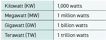
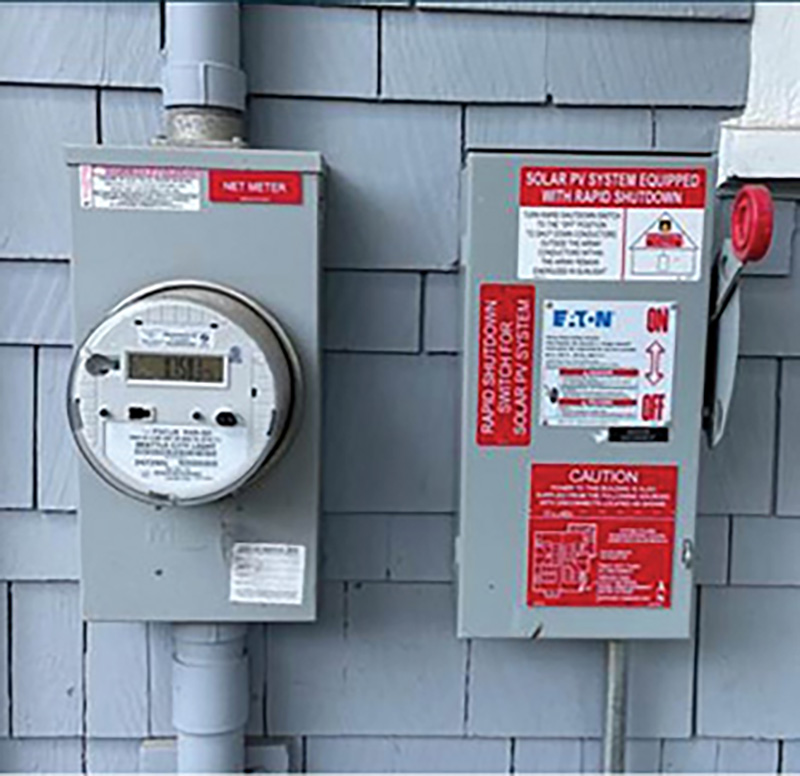
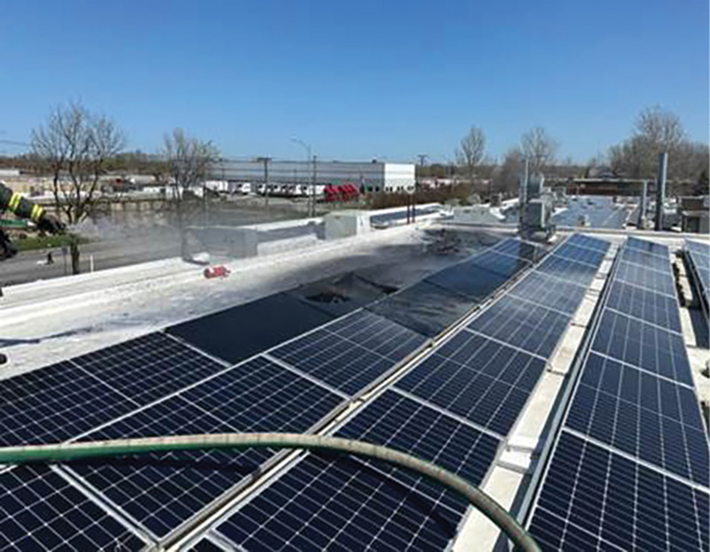
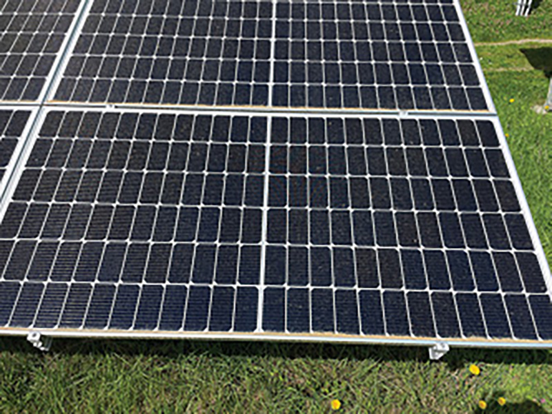
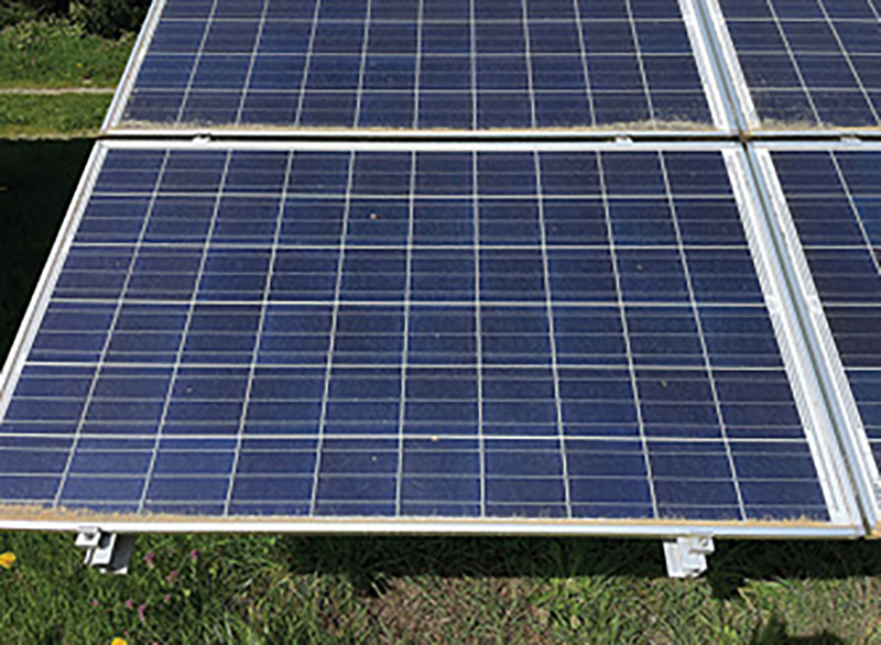
Ground-mounted systems are most commonly associated with large energy infrastructure support. It offers the fire service an initial roadmap of where the systems are and the specific energy guardrails (photos 1, 2, & 3). For example, a PV system atop a single-family residence will have a maximum energy hazard of 600 Vdc. This predictability offers one of the initial building blocks to better understanding this energy hazard.
Electrical Conduit
The electrical conduit houses the energized DC electrical wires. Through this conduit, the wiring connects the array with the inverter. The conduit operates as the energy highway for the system. It is important to note that the wires in the conduit will be energized to the same voltage as the array system. This conduit may be easily seen on the outside of a home or building. In many cases, you’ll find stickers on the conduit, identifying it as Solar or Photovoltaic, or DC or PV. The labeling is an installation requirement for the PV conduit attached to the building’s exterior. However, as structures age, these labels may fade or even be painted over, which makes this safety identifier useless. It is important for crews to understand this inevitability and learn to look for conduits rather than labels.
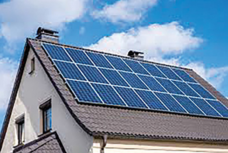
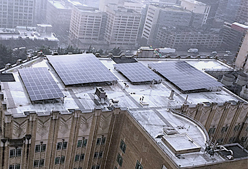
1-3. Maximum voltages for PV arrays are set according to their locations: 1. 600 Vdc. 2. 1,000 Vdc. 3. 1,500 Vdc. (Photos by author unless otherwise noted.)
When a PV’s DC electrical power is routed within the building, as may be the case with new construction, the code expectation is that the DC electrical lines will be in conduit. This runs in conflict with most AC power installations and may offer a clue as to why an attic space contains both electrical conduit and staple attached electrical lines. The DC is required to be in conduit, without exception.
Inverter
The electrical energy created by a PV system will be in the form of DC. This DC energy needs to be converted to alternating current (AC) for use in the structure. That is the purpose of the inverter. The inverter, while integral to PV systems, will result in efficiency degradations. A premium-quality rated inverter will be 90 percent efficient, while a poor-quality inverter may have efficiencies of 80 to 85 percent. This is the piece of a PV system with the largest known losses.
The inverter may have a “shut-off” switch on either side. While this switch serves a maintenance function, it is also a good place for the responder to aid in isolating the system behind the inverter, which keeps the energy from moving into the structure. For large commercial buildings, the inverters and shut-off switches may be located on rooftops adjacent to the panels or, more commonly, on the building exterior. However, with single-family residential systems, they will most commonly be located near the electrical meter. In the residential space, this offers an opportunity for quick identification and isolation of this energy hazard.
Rapid Shutdown
Intended to provide fire service professionals and PV installers with a quick and easy way to reduce the voltage in a PV system to a safe level, rapid shutdown effectively turns off or reduces the voltage of the system at the module level, thereby reducing the shock exposure hazard. The language most often quoted with regards to this feature is as follows: “Rapid shutdown is an electrical safety requirement that was originally introduced in the United States by the National Electrical Code (NEC) in 2014. This requirement applies to solar PV systems and mandates a way to deenergize, or reduce the voltage of, the solar modules on the roof by adding an ‘on/off’ switch, so to speak.” However, meeting the expectations of rapid shutdown has evolved over the past 10 years.
The NEC defines two zones for rapid shutdown. Zone 1 covers the array and all conductors within one foot of said array. Zone 2 covers the conductors between the array and the most accessible disconnection location, such as the inverter or a combiner box. The NEC requires shutdown features for both zones. For Zone 1, the specific safety expectations are that the voltage be reduced to no more than 80 Vdc and 100 volt-amperes within 30 seconds of initiation of rapid shutdown. For Zone 2, the NEC requires voltage to be reduced to no more than 30 Vdc within 10 seconds of initiating rapid shutdown.
Keep in mind that legacy PV systems, installed prior to 2014, are not required to have rapid shutdown features and the current code language is not retroactive. And there is no maintenance or confidence testing requirement for the PVRSE that would ensure that it continues to perform properly over time. Therefore, for the safety of our crews, we need to consider all PV systems energized.
There are two basic components of PV rapid shutdown equipment (PVRSE): a rapid shutdown device (RSD) and an initiator.
- RSD: This type of module-level power electronic (MLPE), often called a microinverter, is located on the back of the PV module. It is designed to turn off and reduce the outgoing voltage from the system consistent with rapid shutdown requirements.
- Initiator: This device is often designed as an emergency shut-off button (E-Stop) and is in or near the inverter. Generally, rapid shutdown may be initiated in two ways: manually, by using the knife switch adjacent to the inverter or activating the E-Stop device, or automatically, when the system loses power (photos 4 & 5).
Key Takeaways
Here are a few important notes about this safety system.
- This feature is not retroactive and not likely present in legacy systems installed prior to 2014.
- Rapid shutdown applies only to rooftop systems, including both single-family residential and commercial roofs. It is not applicable to detached carport-style or ground-mounted systems.
- PV installers report that the commercial application of PVRSE is complicated and inconsistent. Large system installations require a heavy academic load and should only be performed by accredited PV specialists. These PV specialists are in high demand and can be difficult to discern from those of lesser ability.
- The North American Board of Certified Energy Practitioners is a nonprofit professional certification and accreditation organization that promotes consistency in code-compliant training for both PV and solar heat installers.
Electrical Meters for PV Systems
There are three types of metering devices used to account for PV energy: net meters, bidirectional meters, and dual meters. Net meters and bidirectional meters are similar. Both will read the energy received from the grid as well as the PV energy that’s returned to the grid. What is important for our fire crews is that this happens using a single meter.
In the case of dual meters, two separate meters are present: one for energy pulled from the electrical grid and one for PV energy placed back onto the grid. Each city and state may use one or more of the three types, so during your inspection, take note of the types in use.
Dual meters on a single-family residence offer quick insight into the hazard element. Dual meters on the side of that home may represent the presence of a PV array system (photo 6). However, a dual meter may also indicate a sublet or single-family residence that has been converted to a multioccupancy space. Understanding this subtlety can provide valuable information during your initial 360° walk-around. It will also help you create a more robust hazard profile for the incident. For example, the resources needed to search and suppress a fire in a single-family home may not be enough to accomplish these same tasks expeditiously for a multioccupancy home.
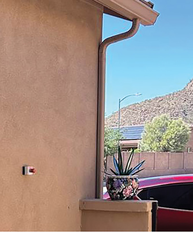
4 & 5. Rapid shutdown initiating devices. Knife switch above, left; E-Stop below. One or both may be present.
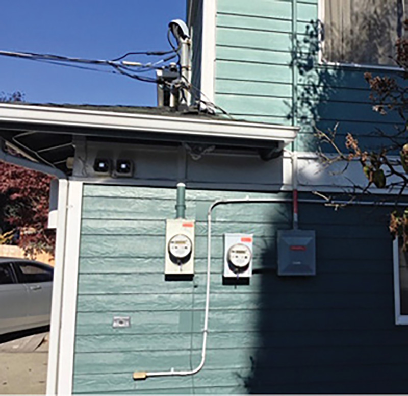
6. Indications of the presence of a PV system include the following: conduit connecting the PV joiner box to the roof, PV labeling on the conduit and utilities, and dual meters measuring the energy pulled from and pushed back onto the grid. Two meters may also serve as an indication of multiple occupancies.
The Nexus Between PV and Battery Energy Storage
PV energy creation offers a clean and clear way to provide a portion of our nation’s energy needs. However, it has a fatal flaw. PV systems have no capacitance. They are truly a “use it or lose it” resource. Energy created by your PV system during the daylight hours, when you are away at work, is pushed back onto the grid. Introducing batteries into this equation allows you to keep what you make.
Creating and containing energy at this level is a type of microgrid, but it doesn’t work without energy storage, aka batteries. Historically, lead acid batteries have occupied this space. However, the current trend is for systems to use lithium-ion batteries, more specifically, lithium-ion iron phosphate (LFP/LiFePO4) cells.
The pairing of PV with battery storage plays an important role as the nation attempts to reduce greenhouse gas emissions. This pairing can be seen in residential, commercial, and industrial settings. It has become so predictable that if you see a PV array system, consider the likelihood of onsite battery storage.
PV projects cannot effectively work without battery energy storage systems (BESS). The BESS regulatory infrastructure reduces the risk of fire and manages hazards associated with failures. In the rare event of a failed system that goes on fire, the regulatory infrastructure once again kicks in with large-scale fire testing, where the goal is validating the reduction of fire spread within the BESS enclosure. The idea of using a two-pronged approach that allows for the fire service to operate safely at an incident when trained properly about the installation is something that NFPA, UL, and IFC codes and standards were able to accomplish through research-based testing and data collection.
Fire Tactical Considerations
Keep in mind the following within the context of PV systems.
- Identify the presence of a PV system as early in the incident as possible. This should be part of your 360. Be sure to clearly communicate this information. For example: “Energy Hazard: Photovoltaic—Rooftop,” or “Energy Hazard: Photovoltaic—Ground-Mounted System, B Side” (photos 7 & 8).
- Locate the isolation switch for the system. It will be near the inverter, near the electrical service meter. Shut the system down by moving the knife switch handle into the off position or activating the rapid shutdown feature via an E-Stop. Both will be located near the inverter. This isolates the electrical energy in the PV system behind the inverter, which in turn keeps it from entering the building. The presence of PVRSE will reduce the voltage in the system to a safe level. If you cannot locate the shutoff, the breaker panel is another option for disabling a PV system.
- Keep energy hazards in mind when you consider ventilation tactics that place members in proximity to PV systems. Alternative ventilation methods that keep members away from these hazards should be part of your risk profile. It should go without saying that deliberately cutting or damaging an array/panel is dangerous and foolish. However, if rooftop vertical ventilation operations are deemed essential, there are some basic energy safeguards to consider. Activate the rapid shutdown feature prior to accessing the roof. Remain at least 12 inches away from all arrays. Locate PV conduit and ensure saws are kept clear. When conduits pass through the roof, their exact location is difficult to track. In these cases, place ventilation cuts no closer than 12 inches from the array/panels. Should the saw contact the PV conduit, it will do so in Zone 2 of the PVRSE. With the rapid shutdown initiated, this zone should be energized to less than 30 Vdc. However, for PV systems not outfitted with PVRSE, and when the conduit cannot be definitively located, consider rooftop ventilation operations an extreme energy risk, and prioritize alternative ventilation methods.
- Keep members positioned at least 20 feet from the hazard for any suppression activities that require water application to PV systems. Ideally, you’ll use a broken stream nozzle at 10° fog. Avoid using foam or salt water, which will increase the electrical conductivity of the hose stream. (See the UL report “Firefighter Safety and Photovoltaic Installation Research Project” for more information.1)
- For post-fire operations, cover any PV arrays system that may have been affected by fire with tarps or black plastic (6 mm). PV arrays do not have a true shutoff. If the sun or your scene lights are shining on them, the panels will produce electrical energy. This creates the potential for an electrical fault and may result in fire.
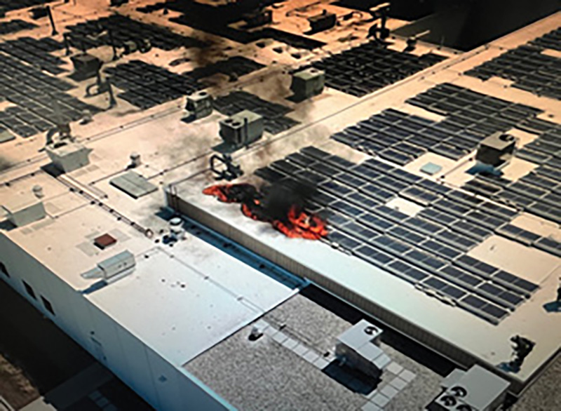
7 & 8. On April 13, 2024, fire crews from the Alsip (IL) Fire Department were dispatched to a roof fire at a large commercial warehouse. They discovered large arrays covering most of the roof. Crews used hoselines and dry chemical extinguishers to control the fire. PVStop was deployed to aid in quickly de-energizing the surrounding panels. PVStop is a liquid spray, discharged from a 2.5-gallon can, designed to block light from PV arrays. (Photos by Rick Kraus.)
Prefire Information
Single-family residential PV systems are relatively predictable, due in large parts to the strictness of residential PV design and installation codes. However, commercial and large-scale systems can be complicated. The most efficient way to prepare for these systems is to capture as much information as possible before there is a problem, during installation or as part of a prefire inspection. Make it available to crews responding to these locations.
Bear in mind that emergency crews may be stressed and exhausted from the previous 20 hours of shift load. So, consider the end user and ensure that the information is readily available and easily understood.
The following list provides some of the most relevant prefire information to consider.
- Type of system: grid-tied, off-grid, hybrid.
- Battery energy storage: location and chemistry type (lead acid or lithium-ion).
- Shut-off/isolation location for PV system. (This may be a breaker or knife switch.)
- Is the system equipped with rapid shutdown features? (This is applicable for newer residential and commercial rooftop systems.)
- What is the maximum voltage: 600, 1,000, or 1,500?
- What is the PV cell type: monocrystalline, polycrystalline, or thin film? (Thin-film types include CdTe, CIGS, and a-Si.)
- Are there multiple independent PV systems?
- Are there diagrams available for system locations relative to the building or property?
9. Monocrystalline has a jet black appearance.
10. Polycrystalline is more of a blue-black color.
The Outlier: Not All PV Material Is the Same
PV cells have traditionally been made from silica (sand) materials. In fact, most systems are made from either monocrystalline silica or polycrystalline silica. The differences between these two are silica purity and techniques in creating the cells themselves.
- Efficiency: Monocrystalline cells are the most efficient cells (25 percent), with polycrystalline cells residing around 18 percent.
- Appearance: Monocrystalline cells will be jet black, while polycrystalline cells have a blue-to-black reflective appearance (photos 9 & 10).
Mono- and polycrystalline are not the only types of cells used to make PV panels. Thin-film cells are on the rise. They now account for more than 10 percent of global PV system installations. Moreover, thin film is heavily used in the ground-mounted infrastructure supportive PV systems. These account for 80 percent of total U.S. PV energy creation, in megawatts. And here’s why this is important: Thin-film cells consist of more than just silica. They are enhanced with a cocktail of other minerals. Here’s an overview.
Cadmium telluride (CdTe) thin-film cells: CdTe photovoltaic cells are used in some of the world’s largest utility scale farms, such as the Topaz PV Farm (500 MW) in California. They comprise 80 percent of the thin-film cell global market. Here in the United States, they account for more than 25 percent of the infrastructure supporting PV farms with capacities at or exceeding 50 MW (Figure 2).
Cadmium is a well-known heavy metal that experts consider extremely toxic. There is an academic gap on how these systems react when they are subjected to fire conditions and failures. This gap should not be overlooked. When we consider the amount of real estate needed to build out our largest PV farms, often requiring hundreds of acres, one can’t help but wonder, “What happens if these cells fracture or burn? What happens with the CdTe elements?” It is difficult to find a study that addresses these concerns, particularly one here in the United States.
Copper indium gallium selenide (CIGS) thin-film cells: CIGS is the second most common type of thin-film cell material. It is used for infrastructure-level PV systems and for small mobile charging devices. And again, studies showing gas data analysis information that might answer some of the same questions for CdTe are proving difficult to find.
Figure 2. Total U.S. PV Energy Production for Systems Greater Than 50 MW
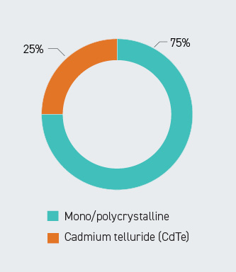
Twenty years ago, cadmium telluride (CdTe) occupied less than 1 percent of the large-scale PV arrays in the United States. Today, it accounts for an impressive 25 percent of that same market space. (Source: Chris G. Greene.)
Wear Your Mask
The thought that PV cells are just silica/glass material and do not represent a potential toxicity hazard may be wishful thinking. In fact, if you encounter a grass fire intruding on a large ground-mounted PV array system, there is a 25 percent chance that the material is CdTe. This would be a great question for you to ask during that system’s installation.
Regardless, in this energy environment, the voltage hazard may be as high as 1500 Vdc, and the off-gassing concerns remain unanswered. So wear your mask. Unfortunately, for our wildland crews who may not be provided with self-contained breathing apparatus, the problems thin film poses are particularly troubling.
Recent Fire Involving Thin-Film PV Cells
On May 13, 2024, a fire involving the rooftop PV system broke out at the Sydney Olympic Park Aquatic Center. The fire consumed a large portion of the 1.3 Mw array. Much of this array was designed using thin-film PV cells. Adding to this concern is the fact that Australian codes do not require rapid shutdown safety features for PV systems. Crews used elevated platforms to control the fire, which was a prudent choice given the absence of PVRSE.
The Washout
In the absence of specific training, the energy hazards present on today’s fireground may be difficult to identify. Furthermore, conducting a risk-benefit analysis with energy in mind will be daunting if you have not invested the time into understanding this hazard.
Sound tactics and comfort on the fireground come from time, deliberation, and training. It takes time to do this job well. We must deliberate on yesterday’s emergencies to ensure that we perform better tomorrow. And we must anticipate and train for future challenges.
I (Greene) believe we have neglected these energy hazards for far too long. Energy hazard training is not extra-credit work. It needs to be part of a baseline fire service curriculum.
ENDNOTE
1. Backstrom, Robert, and Dini, David A. “Firefighter Safety and Photovoltaic Installations Research Project,” UL Solutions, 29 November 2011. bit.ly/4599cYZ.
CHRIS G. GREENE is a captain (ret.) with the Seattle (WA) Fire Department and creator of the Seattle Fire Department’s Energy Response Program.
PAUL ROGERS is a retired lieutenant from the Fire Department of New York (FDNY) where he worked in the hazardous material field, FEMA USAR NY TF-1, IAFF SME, and more. During his time with FDNY, he led a group of fire service experts in developing and writing codes and standards for battery energy storage system (BESS ) installation in New York City. Currently, Rogers represents the fire service on numerous safety codes related to BESS (NFPA 855, UL 9540 , UL 9540 A, and more). After retirement, he helped to create Energy Safety Response Group(ESRG), which advocates for firefighter safety. ESRG has been used in numerous high-profile utility scale BESS failures/fires, where it coordinated with local fire departments through safe operations.

