Cycling Waterflow in Sprinker Systems
FIRE PROTECTION
Detection Problems It Causes And One Plant’s Solution
WHEN BRINGING a new computer-based fire alarm system on line, some problems are expected. For the Paducah Gaseous Diffusion Plant (PGDP) in Paducah, Kentucky, one of the problems had been there all along.
It was in the way the large sprinkler systems in the plant operate. The problem was “cycling” (oscillating) waterflow at the system riser during low flows. This cycling sometimes prevented waterflow detection by the new alarm system. This is because traditional retard (delay) circuitry at the electronic alarm-receiving module assumes a steady flow. The cycling had not been discovered previously due to the slower response time of the old electromechanical alarm system.
Due to the large number and size of plant sprinkler systems, an approach of going directly from symptom to remedy was determined to be the most costeffective. Use of this approach produced a cost savings of more than $200,000 over other, less effective approaches. In addition, operator confidence in the entire alarm system has been restored.
Rather than eliminate the cycling, a modification to sprinkler alarm detection circuitry to detect cycling flows was installed. This modification, costing less than $100 per system, also minimizes the false alarms due to surge conditions in the water supply. After receiving a favorable evaluation from Factory Mutual Research Corporation, the modification was installed in waterflow detection modules in remote terminal units of the new alarm system. Other detection systems having alarm retard circuitry at the alarm-receiving module could be modified in a similar manner.
CYCLING WATERFLOW PROBLEMS
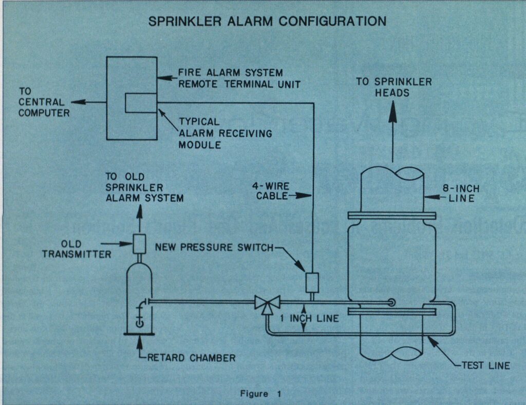
The problem was discovered while cutting over to the new alarm system from a McCulloh-type system. (In a McCulloh-tvpe system, when an alarm condition exists, a spring-loaded codedwheel transmitter taps out a telegraphlike code that represents the alarm number. This number is received at the central station and the location corresponding to the alarm number is looked up in a card file.) After installing a new pressure switch to detect waterflow and connecting it to the new alarm system (see Figure 1, page 52), each sprinkler system was tested.
The test of sprinkler systems required by NFPA 13 requires opening the inspectors test valve (ITV) (this simulates waterflow through one sprinkler head), and NFPA 72D requires receiving an alarm at the central station in 90 seconds. During this test, water flowing through the system riser (where the alarm piping is connected) was found not to be steady, but to flow in “cycles.” (See Figure 2A, page 54). While water is flowing, the clapper valve (which allows water into the alarm piping) is open; while water is not flowing, this valve is closed. This causes the alarm pressure to close and open in response to the cycles. During these cycles, water flows (pressure switch closed) for 4-8 seconds and does not flow (pressure switch open) for 10-35 seconds. The cycling does not affect flow at the ITV.
Two types of systems were tested, Grinnell 8-inch A-Model (1958) and Reliable 8-inch B-Model (1958). Several systems of each manufacturer were tested. Each of the systems covered approximately 37,000 square feet with approximately 300 heads. Both types of systems use 8-inch risers, and the highest branch lines are approximately 90 feet above the clapper valve. There are 130 Grinnell systems in two large process buildings. These buildings cover approximately 27 acres each. There are 70 Reliable systems in two other large process buildings. These buildings cover approximately 14 acres each. Both types of systems use a high-pressure (135-pound-per-square-inch) water supply.

To prevent alarms from being sent on surge conditions caused by pressure fluctuations in the water supply, most sprinkler alarm systems are set to allow a certain amount of retard, or delay, before sending an alarm. However, the alarm condition must be present during the entire delay time for an alarm to be sent. Under a cycling waterflow condition, this will not be the case unless the delay is set to a very short time, because the delay time counter in the alarmreceiving module goes back to zero each time flow ceases. Unfortunately, setting the delay time to a short time will cause an unacceptable number of false alarms due to surges.
Once this cycling was discovered, it was learned that it also was occurring on the old McCulloh system. This system consisted of a pressure switch mounted on top of a retard chamber to allow for a small amount of delay time before sending an alarm. Since this delay time is short and since the McCulloh system is slower than the new alarm system, the problem was not noticed before. The McCulloh system sends in three rounds of code on an alarm, and, when it restores, sends in two more rounds. After discovering the cycling problem, it was found that on the ITV test some of the existing systems would not stay in alarm condition, but would continue sending five rounds, indicating a restoration (see Figure 2B, page 54). This indicated the cycling condition, but it was not recognized until the new alarm system was installed. During system tests, if the first three rounds were sent, the test had been considered good, whether the fourth and fifth rounds were sent or not. The tests had been performed this way for a number of years with no other problems, so it had become the accepted way of conducting the test.
It appears that the cycling is caused by air in the systems. This air seems to provide enough “springiness” in the system to cause oscillations. Other contributing factors seem to be that ITV is on a one-inch line with a one-half-inchorifice and the riser is an 8-inch line. This causes the speed of flow at the riser to be small compared with that at the inspectors test valve. The volume of flow is also small so that the clapper valve is only slightly open during the ITV test. In addition, the alarm line is one inch with a one-half-inch orifice so the amount of water flowing into the alarm piping is significant compared to that through the ITV. Finally, all systems tested have retard chambers. Three systems were tested with the retard chambers valved off, and no cycling was present on the ITV test. When these systems were tested again with the retard chamber valved in, the cycling reappeared.
ALTERNATE SOLUTIONS TO THE PROBLEM
One possible solution to the cycling waterflow problem would have been getting the air out of the sprinkler piping. One possible way of doing this would have been to bleed the air out of the sprinkler system piping. However, due to the large number and large size of the PGDP systems, this would have been impractical. Also, this would have to be done periodically or each time maintenance was performed on a system to assure air did not get back into the piping. Even then, this would be no guarantee that no air was in the system at all times—air that could prevent an alarm from being received. Another possible solution was the installation of air relief devices at several places in each system (see Figure 3, above). However, other such devices used at PGDP have had problems with water leakage. Also, it would have been costprohibitive (approximately S240,000) to install such a large number of air relief devices even if the problem could have been solved this way.


As previously mentioned, valving off the retard chamber prevents cycling. However, this prevents pressure from bleeding off the pressure switch when waterflow ceases and prevents restoration of the alarm until the valve is opened. When the valve was left open any amount for the test, cycling was present. An alarm connection with a drain and no retard chamber was tried and cycling occurred with it also. Closing the bypass line around the clapper valve was also tried, but this also did not prevent cycling.
CORRECTING THE PROBLEM
Since eliminating cycling appeared to be impractical, a way had to be found to receive the alarm w ith cycling present. Since retard circuitry in the alarm-receiving module assumes a steady flow of water, a modification to this circuitry was installed. This modification causes the alarm module to respond to both cycling and steady waterflows. The first waterflow detected starts a delay count of 16 seconds. After 16 seconds, any waterflow detected prior to 64 seconds will produce an alarm condition. If no waterflow is detected from 16 to 64 seconds, the circuit resets. The single surge setting can be doubled to 32 seconds. Furthermore, the waterflow detection time can be set at 128 seconds before circuit reset.
This modification was designed by PGDP Engineering as a “piggyback” circuit board approximately two-inches long by one-and-one-half inches wide. The board may be plugged onto the existing waterflow alarm module (an ADT 4520-329) after minor modifications thereof. Types of waterflow alarm modules other than the one in use at PGDP could be modified in a similar manner. Also, this type of delay circuitry could be incorporated in new alarm module designs.
Circuit boards for the modification cost approximately $10 per system.
Modification of the existing waterflow modules and field installation required approximately two hours per system. Design time for the modification was approximately 80-120 hours, including drafting and circuit board artwork.
Even though some problem exists with every other possible solution, a cost comparison was made between the approach taken and that of installing air relief devices. This alternative was used in the comparison because it would have probably been used had the circuit board modification not been done. Using this comparison, cost savings for the plant were estimated to be S210,000.
Anytime a switchover to a new alarm system is being made, operator confidence in the new system is an important issue. Unfortunately, at PGDP the problem with sprinkler alarms was causing a lack of confidence in the entire system. In addition, prior to correcting the problem, the old coded-wheel-type alarm system had to be used in parallel with the new computer-based system. This was because of the possibility of missing sprinkler alarms or having an unacceptable number of false alarms. Since the modification circuit was installed, monitoring of the old alarm system is no longer required. Removal of this system is planned for the near future. Also, operator confidence in the system has substantially increased.
This report was prepared as an account of work sponsored by an agency of the United States Government. Neither the United States Government nor any agency thereof, nor any of their employees makes any warranty, express or implied, or assumes any legal liability or responsibility for the accuracy, completeness, or usefulness of any information, apparatus, product, or process disclosed, or represents that its use would not infringe privately owned rights. Reference herein to any specific commercial product, process, or service by trade name, trademark, manufacturer, or otherwise, does not necessarily constitute or imply its endorsement, recommendation, or favoring by the United States Government or any agency thereof. The views and opinions of authors expressed herein do not necessarily state or reflect those of the United States Government or any agency thereof.

