
By Bill Gustin
Part 1 appeared in the March 2019 issue.
High-rise fires are high-risk/low-frequency events, and opportunities for many fire departments to participate in intense, high-quality, multicompany standpipe drills are rare. Here, we examine the answers to the following three questions: (1) If standpipe training is infrequent, skill levels are inconsistent, and personnel may have never trained together, why invite confusion by having more than one option for performing a standpipe hose evolution? (2) Wouldn’t there be advantages to performing standpipe operations basically the same way every time? (3) Since options for performing standpipe operations vary according to conditions, why not operate as if conditions were at their worst—smoke and heat are banked down on the fire floor in the public hallway?
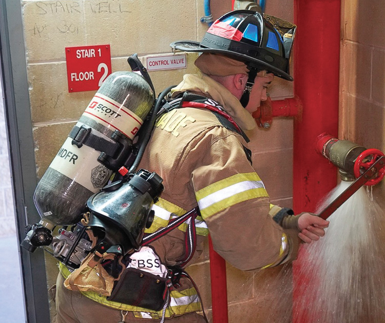
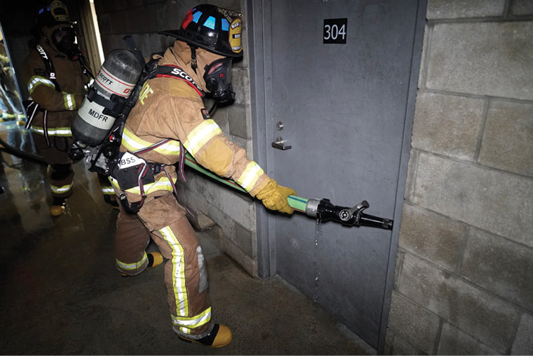
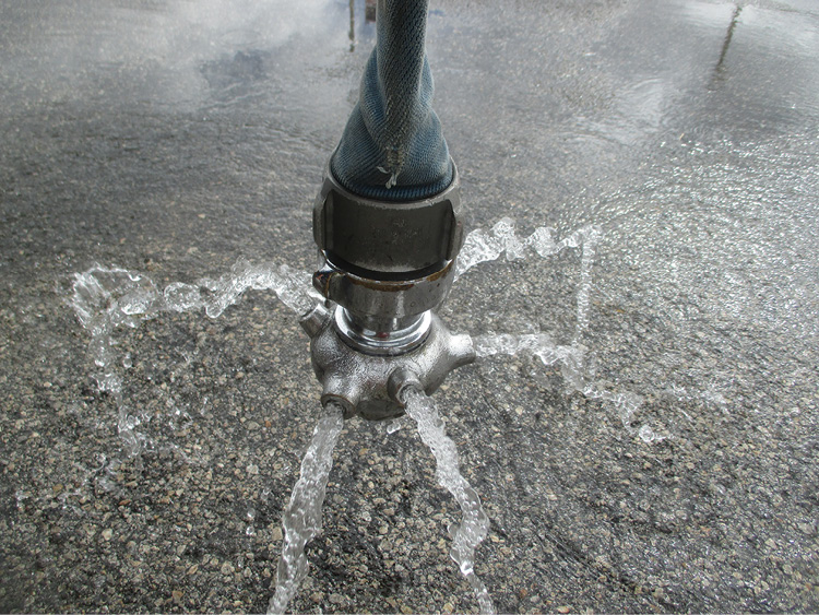
(1) Thoroughly flush a standpipe outlet to clear it of rocks, sediment, and debris. Don’t let occupants get caught in the waterfall and be swept down the stairs. (Photos by Ricardo Stephens unless otherwise noted.)
RELATED
What Firefighters Must Know About Fire Protection Systems, Part 1
What Firefighters Must Know About Fire Protection Systems, Part 2
Charging the Line
Under these conditions, the hoseline must be charged before leaving the refuge of the attack stairwell and advancing on the fire floor. If firefighters consistently perform standpipe hose evolutions as if they are prepared for the worst conditions and then find conditions better than anticipated, they will not be taken by surprise. There’s no argument that it takes less time and physical exertion and fewer personnel to stretch an uncharged hoseline upstairs to the fire compartment, but this can result in confusion as to when to charge the line and properly adjust its pressure. Don’t rely on radio communication to advise the firefighter at the standpipe outlet when to charge the line and adjust its pressure because radio traffic at that stage of the incident is usually excessive. Charging the hoseline with the nozzle at the standpipe outlet prevents this confusion.
Do not rely entirely on an in-line gauge to judge the proper pressure because gauges are known to be notoriously inaccurate. Instead, practice relying on the judgment of an experienced nozzle firefighter and company officer to assess the flow of their stream based on nozzle reaction and reach. It’s a good drill to have the nozzle firefighter assess the quality of his stream and then take a look at the gauge. Remember that static pressure on an in-line gauge is meaningless; head pressure of the water column in the standpipe above the outlet or the pressure developed by the building’s jockey pump can fool firefighters who fail to fully flow the hoseline when adjusting the pressure. There’s no question that fully flowing the hoseline on the floor below the fire can be problematic because of where the water may go. If the nozzle is opened in the stairwell, there is a risk of washing evacuating occupants down the stairs; hence, occupants must be directed to vacate the attack stairway. Additionally, it is very important to thoroughly flush a standpipe outlet to clear it of rocks, sediment, and debris; but don’t let occupants get caught in the waterfall and be swept down the stairs (photo 1).
When adjusting pressure, firefighters may choose to flow their hoseline in the public hallway on the floor below the fire, immediately outside the stairwell. In this case, they must avoid directing their stream toward elevator hoistways and meter and mechanical rooms. When the nozzle firefighter and the firefighter adjusting pressure at the standpipe outlet are in visual and verbal contact, they can agree on the quality of the stream. Additionally, they can identify and correct any pressure problems in the system before the hoseline ascends to the fire floor.
Two-Inch Standpipe Hose Evolution
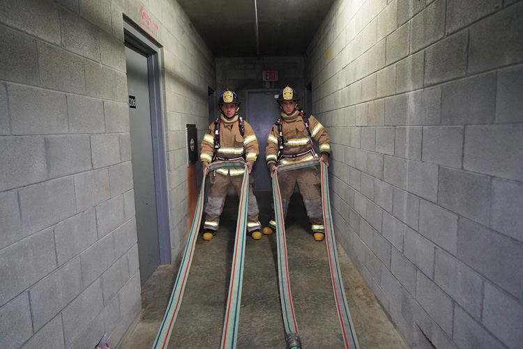
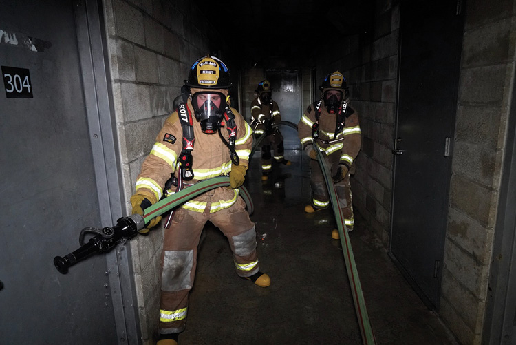
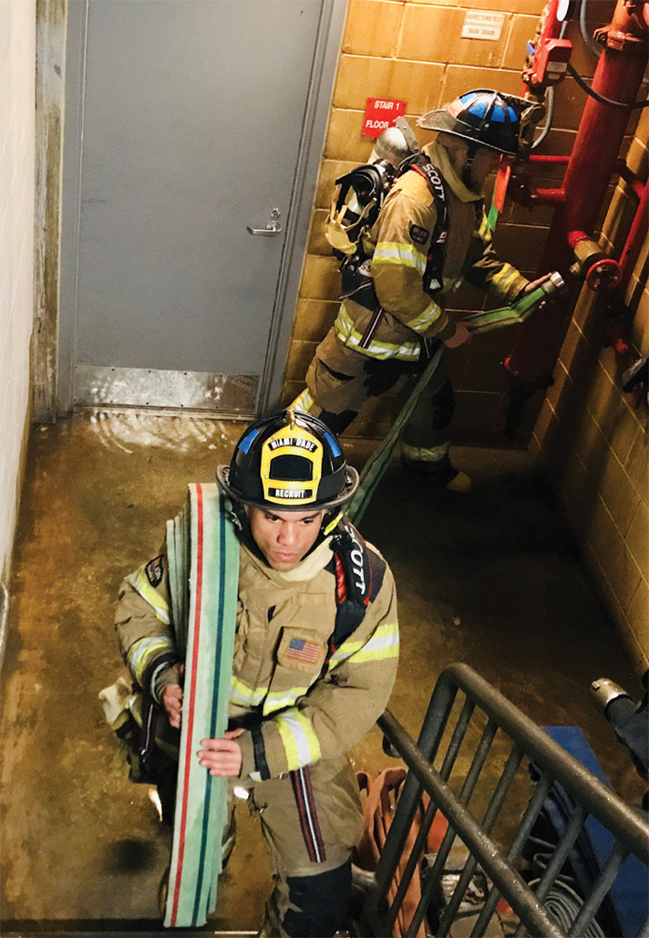
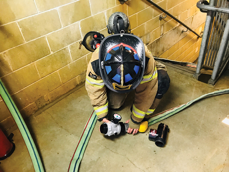
As discussed in Part 1, Miami-Dade (FL) Fire-Rescue’s 75-foot sections of two-inch hose are configured in a simple accordion bundle fold that is bent in half to form a horseshoe that can be carried over a firefighter’s shoulder or self-contained breathing apparatus (SCBA) cylinder. The hose is commonly deployed in the following manner: The three bundles with all female couplings facing in the direction of the standpipe outlet are laid side by side in the public hallway just outside the stair landing on the floor below the fire floor. After making connections (photo 2), the officer grasps the nozzle and a fold in the middle of the stretch—that is, at the midpoint of the middle bundle (photo 3). One or two firefighters then pull the two couplings down the hallway (photo 4). As the loops of hose tighten, the firefighters pull them, hand over hand, from the bottom to form a “W” (photo 5). In narrow hallways, they place the leading portion of the stretch, closest to the nozzle, on top so it slides over the hose remaining in the hallway. Once pressure is adjusted and members are in agreement on the quality of the nozzle’s stream (photo 6), the nozzle team consisting of at least an officer and two firefighters will ascend the stairs to the fire floor (photo 7).
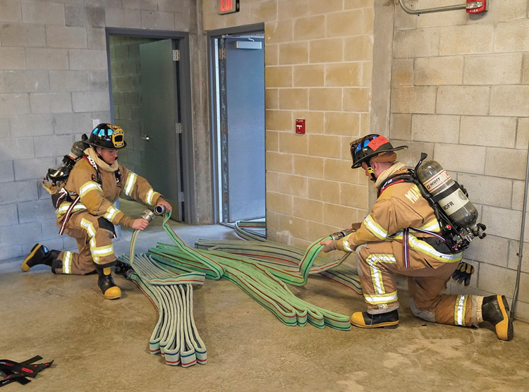
(2) Connecting three 75-foot bundles. Notice that the female couplings are facing the source of the water and the standpipe outlet is in the stairwell.
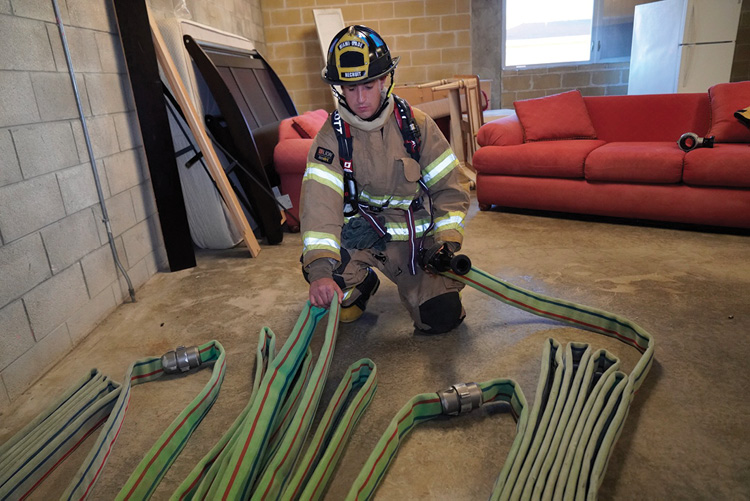
(3) The officer secures the hose during the stretch by grasping the nozzle and the middle of the load.
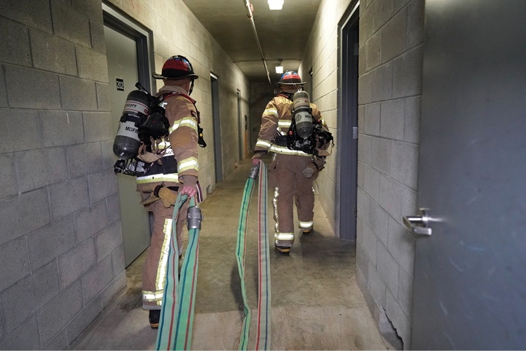
(4) Firefighters pull the couplings down the hallway.
(5) The hoseline forms a “W” configuration in the hallway, which eliminates slack and prevents kinks.
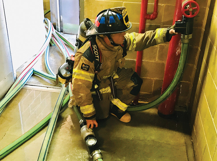
(6) Firefighters charge the hoseline with the nozzle flowing at the standpipe outlet. The nozzle will not ascend to the fire floor before the nozzle firefighter and the firefighter opening the outlet agree on the pressure and the quality of the stream.
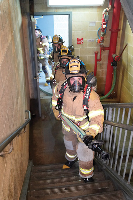
(7) The nozzle team ascends the stairs to the fire floor with a charged hoseline.
Note: Before opening a stairwell door separating a tenable stairwell from a smoke-filled public hallway, it is critical that occupants are evacuated from the attack stairwell, even if it delays advancing a hoseline to the fire. Under these conditions, opening the door to the public hallway will turn the stairwell into a chimney.
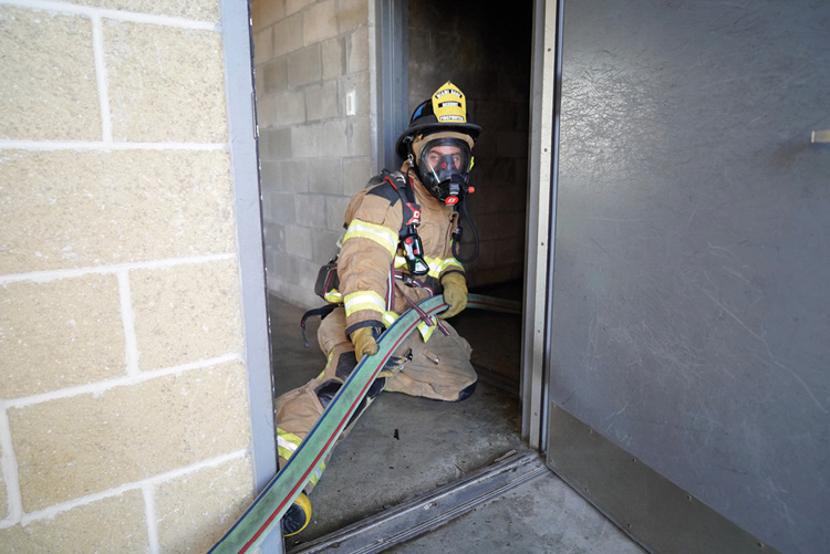
Once the hoseline reaches the fire floor, the third firefighter with the nozzle team will operate somewhere between the attack stairwell and the fire compartment to “lighten up” on the line. Additionally, if there is a corner in the public hallway, the third firefighter will take a position there to manage the hoseline’s change of direction. Ultimately, the third firefighter will assume the door position, feeding hose from the hallway into the fire compartment (photo 8).
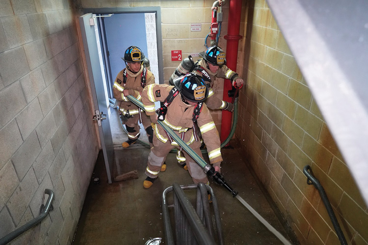
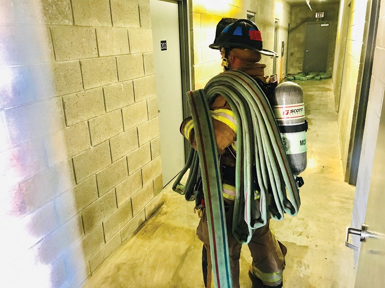
In addition to the nozzle team, it will take a team of at least three firefighters, affectionately called “mules,” to keep the hose moving toward the fire. One mule pulls the hose from the floor below (photo 9) and feeds it to a second mule at the stair mid-landing (photo 10), who, in turn, feeds it to a third mule positioned at the fire floor landing (photo 11), who feeds it to the nozzle team advancing down the public hallway. Additionally, assign a firefighter to monitor the in-line gauge and adjust the pressure. If no firefighter is available to exclusively monitor the in-line gauge, then, by default, it becomes the responsibility of the mule on the floor below to read the gauge as frequently as possible.

(8) The door firefighter pulls the hose from the fire-floor hallway and feeds it to the nozzle team advancing in the fire compartment.

(9) A “mule” operating on the floor below the fire. The mule pulls the hose laid in the hallway and feeds it to a mule operating at mid-landing

(10), who, in turn, feeds it to the mule operating at the fire floor landing (11).
The role of mule firefighter exemplifies the need for discipline and teamwork in standpipe hose evolutions. Clearly, most firefighters performing the task of a mule would rather be on the nozzle, but it is doubtful whether the nozzle will make it to the fire if all personnel are bunched up at the end of the hoseline. It is important to clarify that this evolution requires a bare minimum of six individuals who mean business; that does not consider the number of relief personnel needed to sustain the operation. Additionally, an increase in the diameter of the hose, the length of the hallway, and the number of corners will require additional personnel.
If smoke conditions in the public hallway permit personnel to stand or at least crouch and still see their feet, they can use their leg muscles to pull sufficient hose—at least 50 feet—so that every point in the fire compartment is within range of the nozzle’s stream before they make entry. Doors in multiple-dwelling units typically open inward against the wall separating them from adjoining units. Positioning the nozzle and the hose on the hinge side of the door gives the nozzle team a straight shot into the fire compartment. If fire is directly behind the door, the nozzle firefighter can direct a stream when the door is open just a few inches.
Conversely, if the nozzle is positioned on the latch side of the door, firefighters may see flames and direct their stream, but they will not get water on the fuel that is producing the flames until their hoseline makes an abrupt 180° turn. When the nozzle team advancing the hoseline first encounters the latch side of the door, they should jam the tip of the nozzle against the door frame on the hinge side and, using the door frame as a fulcrum, pivot the nozzle so its stream can be directed from the hinge side and use the momentum of the advancing hoseline to change its direction, pulling a loop of at least 50 feet of hose behind the nozzle (photos 12-13). This technique, which is most easily performed when the door to the fire compartment is closed, gives firefighters the opportunity to pull up sufficient hose and then chock (photo 14) the stairwell door open just enough for the hoseline to fit before they force the door to the fire compartment (photo 15). This significantly reduces the width of the stairwell door opening, limiting the amount of smoke entering the stairwell and making the building’s stairwell pressurization system or the fire department’s blowers to pressurize a stairwell more effective.
(12) The nozzle team advancing the hoseline first encounters the latch side of the door. The nozzle is jammed against the door frame on the hinged side and
(13) the team pivots so that the nozzle and the hose pulled behind it have a straight shot into the fire compartment.
(14) Once sufficient hose is advanced to the door to the fire compartment, the stairwell door can be chocked just enough for the hose, significantly reducing the amount of smoke entering the stairwell and enhancing the effects of stairwell pressurization.
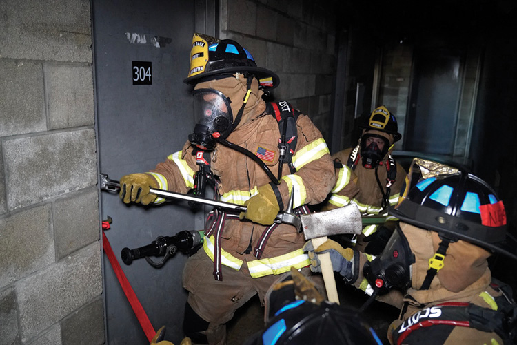
(15) Forcing entry while controlling the door. The nozzle and sufficient hose for its stream to reach any point in the fire compartment are at the ready.
Replacing the Wye with a Hydrant Gate Valve
With the introduction of two-inch hose, Miami-Dade will discontinue the use of a 2½- × 2½- × 2½-inch wye for standpipe operations. In addition to being as heavy as a boat anchor when carried upstairs in a standpipe accessory bag, its use is not in accordance with National Fire Protection Association (NFPA) 14, Standard for the Installation of Standpipe and Hose Systems, which requires a minimum flow of 250 gallons per minute (gpm) per standpipe outlet, for a total flow of 500 gpm from two outlets per standpipe. There’s no argument that many standpipe systems will flow substantially more than 250 gpm per outlet, sufficient to supply a portable master stream device. But there is no requirement; hence, no guarantee. Since we should not expect a flow greater than 250 gpm from a single standpipe outlet, a second hoseline would have to be connected to a second outlet. The department replaced the wyes with lightweight hydrant gate valves to facilitate operating a second hoseline from a standpipe using the following steps.
Procedure
- With the first hoseline connected, stretched, and charged from an outlet on the floor below the fire, connect a section of hose to an outlet two floors below the fire floor. Note that in photo 16, the standpipe bundles can also deploy from a firefighter’s forearm or shoulder because they are configured in a horseshoe beginning with the male coupling.
- Stretch the section to the stair landing on the floor below the fire.
- Connect the gate valve to the hose and the in-line gauge to the outlet of the gate valve (photo 17).
- With the gate valve closed, fully open the standpipe outlet two floors below the fire floor.
The gate valve, in essence, extends the standpipe outlet two floors below the fire floor to the floor below the fire. This allows one firefighter to control the flow to both hoselines by reading the in-line gauges of each line and adjusting pressures on the outlet and gate valve (photo 18).
Charging a second hoseline from a standpipe. (16) Connect the hose bundle to an outlet two floors below the fire and stretch it up the stairs. (Photos 16-18 by Shawn Thompson.)
(17) Connect the gate valve and in-line gauge on the stair landing of the floor below the fire.
(18) Charge the second line by opening the gate valve while focusing on the pressure gauge of the first hoseline.
Note: Charging a second hoseline has the effect of “stealing” water from the first line, reducing its pressure. It is, therefore, critical to charge and flow the second line with the first line flowing. When charging the second line, the firefighter opening the gate valve should focus on the first line’s in-line gauge. If there is a reduction of pressure, he should stop charging the second line until the pressure to the first line is restored by further opening the standpipe outlet.
“Relocating” a Standpipe Outlet
The hydrant gate valve can also be used to relocate the closest, serviceable standpipe outlet in the following situations.
In many jurisdictions, including Miami-Dade, codes require only one functioning standpipe in buildings under construction regardless of the building’s footprint. As a consequence, the construction standpipe could be hundreds of feet away from a fire. If this is the case, team up companies to stretch 2½- or three-inch hose from the construction standpipe to where the hose bundles will be deployed, connect a gate valve, fully open the construction standpipe’s outlet, and control the flow remotely at the gate valve as if it were a standpipe outlet. This obviously would require fire companies to have prefire intelligence. They should be visiting the construction site daily to check, among other things, the status of the construction standpipe.
Similarly, in cases where the entire standpipe is faulty because it is clogged with rocks and debris or there is a closed valve that firefighters cannot locate, stretch from a serviceable standpipe in another stairwell to the attack stairwell, and connect a gate valve (photo 19).
(19) Stretching the bundle from the functioning standpipe to the attack stairwell without a functioning standpipe. Note the hose bundles in the hallway outside the attack stairwell door. (Photo by Shawn Thompson.)
In old buildings where standpipe outlets are in cabinets in the public hallway a considerable distance from the attack stairway, stretch from the cabinet to the attack stairway, and connect a gate valve.
In cases of a faulty standpipe outlet—for example, with damaged hose threads—connect and stretch hose from a functioning outlet two floors below the fire, and connect a gate valve on the floor below the fire.
Stretching in Tall, Skinny Buildings
There is a trend in the construction industry to build residential buildings with extreme width-to-height ratios. The result is that buildings have a very small footprint (so it can fit in a small urban lot) but are as much as 1,000 feet tall with a profile resembling a pencil. With limited floor area, it is common to find very few or just one residence per floor in some luxury high rises. This presents a problem for firefighters because these buildings have very small, if any, public hallways in which to stretch hose. In a city bordering Miami-Dade’s jurisdiction, there is a luxury condominium building where each floor, except the first, consists of just one 3,200-square-foot residence. Consider the dilemma that firefighters will face in this building: If they choose to take the elevator to a floor below the fire, they will find themselves arriving in a very small elevator lobby looking at the door to a single residence. The building’s two stairwells are not accessible from the elevator lobby; they must be reached by forcing entry to a residence. In tall, slender buildings, firefighters will have to decide whether to stretch hose in a stairwell, in a residence on the floor below the fire, or both. In photo 20, firefighter recruits meticulously laid horseshoe bundles of hose, playing off their shoulders in a circular fashion in a small space room simulating an apartment below the fire adjacent to the attack stairwell. There’s nothing fast about this method; recruits are taught that they must take the time to meticulously lay the hose. If they rush and charge the hoseline prematurely before removing potential kinks, they will end up with a twisted gaggle of kinks.
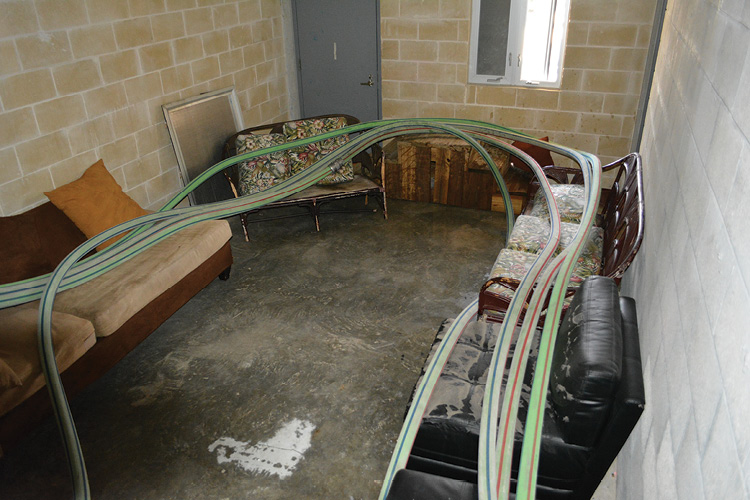
(20) The hose is laid out in a circular fashion on furniture in an “apartment” in a training tower. (Photo by Matt Livingstone.)
Deploying a Rotating Distributor Nozzle
Learning the technique from Canadian firefighters, Miami-Dade began experimenting with lowering a hoseline connected to a rotating distributor nozzle. For years, we had been looking for a solution to two high-rise firefighting problems: wind-driven fires and fire spread from balconies involving patio furniture. Drilling with the Canadian technique, we have found that the stronger the wind, the greater the amount of water and the greater the distance the wind will push water into a building—in effect, “wind-driven water” (photos 21-22). In the Miami area, large waterfront condominium units tend to have large balconies loaded with patio furniture. Some of this furniture, designed to remain outdoors, is essentially solidified gasoline. Consider that faux wicker and rattan, waterproof upholstery, and foam rubber padding in patio furniture are most likely made from hydrocarbon-based petrochemical materials. Not only will burning patio furniture autoexpose balconies above the fire, but also molten plastic will spread fire downward because it is essentially a running, three-dimensional hydrocarbon spill fire. Say a leaking barbeque propane tank starts a fire on the balcony of apartment 1506. Soon burning, melting patio furniture has spread fire to the balconies of apartments 1406, 1606, and 1706; above and below the original fire. In this situation, one company, calculating the rate of fire spread and the time it will take them to get water on the fire, forces entry into an apartment above the fire and stops the fire’s vertical extension by lowering a spinning distributor nozzle flowing 250 gpm.
(21) A close-up of a Bresnan distributor nozzle, which rotates as water is discharged through the holes.
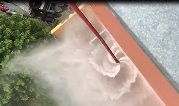
(22) The Bresnan distributor discharging in a vortex while lowered over the side of the training tower.
(23) The hose is strangled by nylon webbing. (Photos 23-25 by Matt Livingstone.)
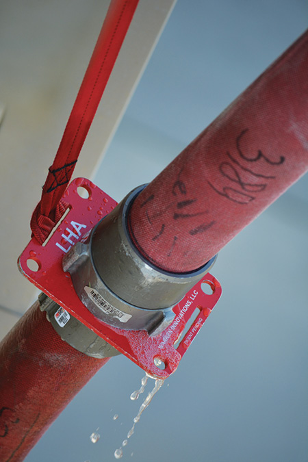
(24) A close-up of the hose suspension plate.
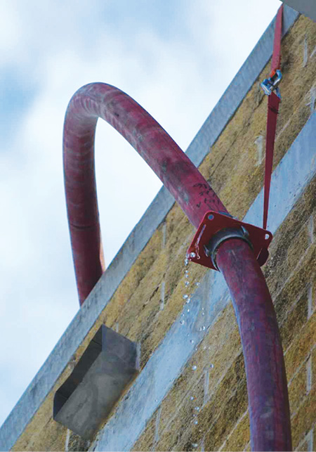
(25) A more distant view of the suspension plate showing how the hose is supported, which allows the hose to bend from the side of the building to the roof without kinking.
Improvising a “Portable Standpipe”
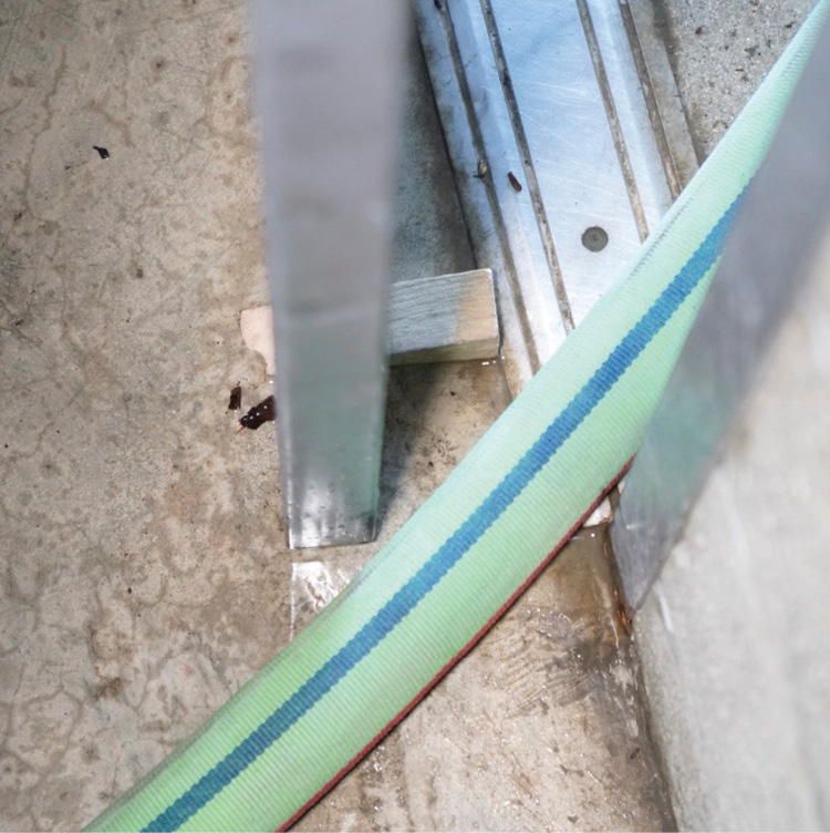
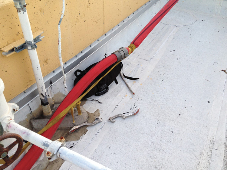
When a fire occurs on a lower floor of a high-rise building, dropping a rope bag and hoisting a hoseline supplied directly from apparatus may be preferred over relying on an inherently unreliable standpipe system. Similarly, dropping a rope and hoisting a hoseline is an expedient way of bypassing a standpipe in a total system failure. Hoisting hose, however, becomes difficult above the 10th floor because the hose becomes heavy. Although the weight issue can be largely avoided by lowering hose instead of attempting to raise it, securing hose without kinks or restrictions can be a problem. The hose in photo 23 is a result of my company’s first attempt in lowering hose from the roof of a 16-story building. When it was charged, its weight tightened the tubular webbing, securing it to a point that it strangled the hose and severely kinked it where it rose over the parapet.
Through trial and error and through networking with firefighters in New York and Clark County, Nevada, we found that the key to eliminating kinks and restrictions is to support the uppermost suspended coupling. This transfers the weight of all but the uppermost section of hose to rope and tubular webbing. Since there is no weight pulling on the uppermost section of hose, when it is charged it is free to form a gradual arc with no kinks where it rises over a windowsill or parapet. The hose in photos 24 and 25 is supported by a “suspension plate,” a device designed specifically to support hose lowered over the side of a building; a patent is pending. The plate placed between the male and female couplings transfers the weight of all but the uppermost section of a rope and attached tubular webbing without any restriction.
It’s important to understand that supporting hose at just one coupling is intended primarily for curtain wall buildings where couplings at intermediate levels cannot be supported without breaking glass. Clearly, if a building has a large well opening in a stairwell, secure couplings at intermediate levels with webbing or a rope hose tool.
Tip: On windy days, use small-diameter rope to tether the hose to keep it from breaking windows when it is being lowered.
The limit on how high hose can be lowered and charged remains to be seen. In the Las Vegas area, the Clark County Fire Department successfully improvised a standpipe by lowering a 2½-inch hose from the roof of a 23-story building. Considering that modern, high-quality fire hose has remarkable strength, I think the limit will be much higher than 23 stories.
A word of caution: The forces of gravity and pressure make this an inherently dangerous operation; conduct it in accordance with an ongoing risk vs. benefit analysis. If the operation is indicated, avoid using older hose with questionable strength, stand clear of the hose when it is charged, and secure the end where flow is controlled by a wye or a gate valve. On the ground, establish an isolated area should the hose separate at its couplings and fall.
Bill Gustin is a 46-year veteran of the fire service and a captain with the Miami-Dade (FL) Fire/Rescue Department. He began his fire service career in the Chicago area and is a lead instructor in his department’s Officer Development Program. He teaches tactics and company officer training programs throughout North America. He is an advisory board member of FDIC International and a technical editor of Fire Engineering.

