By Joseph R. Polenzani
Running the pump on a fire scene can be one of the most challenging jobs in the fire service. Competent pump operators must know the basic principles of hydraulics, the specifications and capabilities of their apparatus and its quirks (aka “features”), the specifications of other apparatus in the department, how to determine friction loss, departmental standard operating procedures/guidelines, how to read the gauges and troubleshoot problems, and where to find everything on the rig.
Many departments have ranked or titled personnel, known as chauffeurs, drivers, or engineers, who are responsible for all apparatus operations. These departments may be very strict about qualifying members to drive; they may require state or local certification or even commercial driver’s licenses.
Often, however, the apparatus operator may be determined by who is on duty or available at the time of the call, regardless of whether or not they are properly trained. Many firefighters have been taught just enough about their apparatus to enable them to get water to flow out of the nozzle most of the time. In these cases, there is a good chance that their crew’s attack lines may get overpumped, underpumped, or possibly not pumped at all!
Proper pump discharge pressures (PDPs) are an essential part of successful fireground operations. Overcharged lines can result in burst hoses; reduced maneuverability; or even injuries from excessive, unexpected nozzle reaction. On the other hand, a PDP that is too low will not deliver the gallons per minute (gpm) needed for effective fire suppression.
For an inexperienced pump operator, calculating friction loss on the fly is often the most intimidating and stressful part of the job, and fixating on it may cause the operator to overlook critical problems, such as hose kinks or an insufficient water supply. Although there is no substitute for a solid understanding of fireground hydraulics, rules of thumb are a great way for novice pump operators to quickly set safe and effective fire flows. These flows can then be fine-tuned as time and conditions allow. Rules of thumb can also be used by more experienced pump operators to quickly double-check their “real” friction loss calculations or verify that another engineer’s numbers are at least in the ballpark.
Rule of Thumb for Quick Water
Here’s my favorite rule of thumb for getting quick water at 3:00 a.m. I call it “12-20-25.” I’ll explain the rule using some common fireground equations.
There are a number of friction loss formulas in use by the fire service. Examples include the National Board of Fire Underwriters formula (2Q2+Q), the “condensed Q” formula for three-, four-, and five-inch hose (Q2), and the modern coefficient formula (CQ2L). All of these formulas calculate the amount of friction loss in a fire hose based on three variables: the diameter of the hose, the length of the hose, and the volume of water being sent through the hose.
For this article, we will use the friction loss formula CQ2L, where
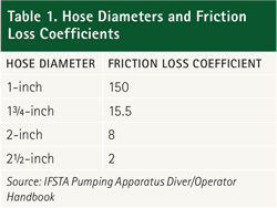
- C is a friction loss coefficient based on hose diameter, measured in inches;
- Q is the flow in gpm divided by 100; and
- L is the hose length in hundreds of feet (you can also think of L as hose length divided by 100, if that’s easier).1
One of the little-known advantages of the CQ2L formula is that the coefficients can be adjusted based on the results of real-world flow testing (more on this later). However, to begin, we’ll use the standard friction loss coefficients shown in Table 1.
As an example, for a 200-foot, 1¾-inch hose flowing 160 gpm, the equation is
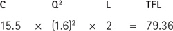
Let’s round that up to 80 pounds per square inch (psi), for simplicity. Pump discharge pressure (PDP) is calculated by adding the nozzle pressure (NP) to the total friction loss (TFL) calculated above. Since our smooth bore handline nozzles are being pumped at 50 psi, our PDP calculation is
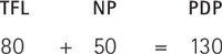
So, for a 200-foot, 1¾-inch hose with a 160-gpm nozzle, our pump’s discharge gauge should be reading 130 psi. Don’t get too bogged down in the math right now. The idea is to see where the rule-of-thumb numbers come from so you can adjust them (if desired) to suit your department’s needs.
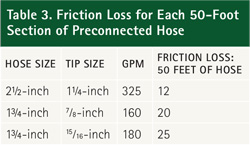
The hose loads my department carries are pretty typical for our part of the country: preconnected 1¾-inch lines with either smooth bore tips (7⁄8-inch or 15⁄16-inch) or automatics. We also carry 2½-inch preconnects with the traditional one-, 11⁄8-, and 1¼-inch stacked tips. Although this method is based on smooth bore nozzles, we’ll see that the same principles can be applied with automatic nozzles.
We’ll start with the smooth bores. Using the CQ2L formula, the flow and friction loss figures for each section of our preconnected lines are shown in Table 2.
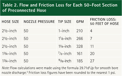
It’s important to bear in mind that the friction loss figures on this chart are for 50-foot hose sections, not 100 feet of length, like you’d normally use when calculating friction loss with CQ2L or other formulas. I suppose you could double the numbers for 100 feet, but then you would have the “24-40-50 Rule,” and you’d have to divide one of them in half for 150-foot and 250-foot lines. That’s way too much math for me. We’re also going to do a little rounding, so we can work with easy-to-remember figures.
Now that we have our numbers, let’s put the rule to work. For the 2½-inch line, the first thing you need to do is pull the one-inch and 11⁄8-inch tips off of the stack. A 2½-inch handline is a powerful fire suppression tool. However, when a 1¾-inch line can flow more than 180 gpm, there’s little point in dragging around the big hose if you’re only getting an extra 30 gpm.
To find a good starting PDP for our 2½-inch attack line, we need to count the number of 50-foot sections of hose, multiply that number by 12, and then add 50 psi for the nozzle. Using our rule of thumb for a 200-foot 2½-inch attack line with a 1¼-inch tip, the figures would be
48 psi loss (four sections at 12 psi each) + 50 psi NP = 96 psi PDP
For 1¾-inch lines with 7⁄8-inch smooth bore tips, count the number of 50-foot sections of hose, multiply that number by 20, and add 50 psi for the nozzle. Using our rule of thumb for a 200-foot 1¾-inch attack line, the figures would be
80 psi loss (four sections at 20 psi each) + 50 psi NP = 130 psi PDP
If you use 1¾-inch lines with 15⁄16-inch smooth bore tips, it works the same way: Count the number of 50-foot sections of hose, but this time multiply that number by 25 and then add 50 psi for the nozzle. Using our rule of thumb for a 200-foot, 1¾-inch attack line, the figures would be
100 psi loss (four sections at 25 psi each) + 50 psi NP = 150 psi PDP.
(12-20-25…see?)
Fog Nozzles
Since automatic nozzles will adjust their flow based on pressure, the same friction loss figures apply if you use the same target flows (328, 161, and 185 gpm). Just be sure to add another 50 psi nozzle pressure (for standard 100-psi fog tips). The 12-20-25 rule will also work with single-gallonage or selectable-gallonage nozzles, provided that target flows are comparable. If the engineer pumps a 175-gpm fog nozzle using the friction loss calculations for 185 gpm, the attack crew will still have all the water they need.
Friction Loss Caveats
Sharp-eyed personnel will probably have noticed that these calculations don’t include friction loss changes caused by elevation. That’s true. Just remember that the intent of this rule of thumb is to allow pump operators to quickly determine a safe and effective initial PDP. Realistically speaking, by the time a handline can be stretched to the second or third floor of a structure, a pump operator with even the most rudimentary skills should be able to add another five to 10 psi to offset the loss.
It’s also true that the “standard” friction loss formulas aren’t accurate for all sizes and brands of hose. The friction loss characteristics of fire hose are primarily determined by two factors: the smoothness of the interior surface of the hose and the hose’s interior diameter (the C coefficient in CQ2L attempts to account for both of these variables with a single value). Unfortunately, both of these factors are subject to wide variations, depending on the construction and condition of the hose.
In 2010 and 2011, the Fire Protection Research Foundation tested 82 samples of fire hose in an effort to determine the friction loss characteristics of modern hoses. Researchers found that the actual coefficient (C) values for new hoses were very different from the standard values shown in Table 1. For example, the customary C value for 2½-inch hose is 2. The 17 2½-inch hoses tested by the Foundation had calculated C values ranging from a low of 1.08 to a high of 2.22.3 Using hose with a 1.08 C value, the 12 in our rule of thumb would become a 6!
Remember, though, this testing was conducted using new samples of modern hose. Over time, changes in the hose caused by deterioration or damage will have a negative effect on its friction loss characteristics. The only way to know with absolute certainty what kind of gpm your crews are delivering is to test your pump, your hose, and your nozzle using a flowmeter or pitot tube and gauge. You can then calculate a C value that accurately reflects the equipment your company uses.
That being said, many departments unknowingly underpump their attack lines on a regular basis. If your department’s pump operators are using friction loss figures that are substantially lower than the ones above, you should probably verify that you’re actually getting the volume of water you think you’re getting.
The 12-20-25 rule can also be modified to work with your department’s preferred hose and nozzle combinations. For example, if your department takes advantage of the enhanced maneuverability and control of a 11⁄8-inch tip on its 2½-inch lines, the 12 would become a 7. “7-20-25” is still pretty easy to remember. Regardless of the specific numbers, the goal is to have three figures that the pump operator can use to “preplan” the preconnected or frequently used lines on the apparatus.
Running a fire pump will never be a simple task. Although a computerized control panel has replaced the vernier throttle and manually set relief valve on many modern fire apparatus, pump operators will always be responsible for performing a complex job under stressful and distracting conditions. Although rules of thumb may not provide decimal point-perfect friction loss figures, they do allow pump operators to get their eyes off the calculator, chart, or cheat sheet and focus on their primary contribution to firefighter safety: managing water flow on the fireground.
Endnotes
1. Goodson, Carl and Brakhage, Cindy, eds. Pumping Apparatus Driver/Operator Handbook (Stillwater, OK: Fire Protection Publications, 2006), 185-186.
2. The full formula for calculating flow through an orifice (such as a smooth bore nozzle) is acdd2√p, where “a” is a constant, “cd” is the coefficient of discharge, “d” is the orifice diameter measured in inches, and “p” is the pressure at the orifice (nozzle tip). Because the cd value for smoothbore nozzles is typically so close to 1 (0.96-0.997), most “fireground” formulas omit the coefficient of discharge from the equation. Civil Engineer John R. Freeman calculated the value of “a” as 29.71 in 1888; the “Freeman Formula” (29.71d2√p) is still in widespread use today. However, other values for “a” are also found throughout the fire service. Examples include 29.83 (American Insurance Association), 29.84 (NFPA Fire Protection Handbook), and the abbreviated 29.7 version used by both IFSTA and Jones & Bartlett.
3. Scheffey, Joseph L; Eric W Forssell; and Matthew E Benfer, Determination of Fire Hose Friction Loss Characteristics (Quincy, MA: Fire Protection Research Foundation, 2013), 17, 31.
JOSEPH R. POLENZANI is a 23-year veteran of the fire service, a battalion chief with the Franklin (TN) Fire Department, and a volunteer firefighter with the Williamson County (TN) Rescue Squad. He is a recruit instructor and has served as chairman of Franklin’s training committee. He has a bachelor’s degree in fire administration and is a certified fire officer II, safety officer, and instructor.
Water Supply: Preplanning Alternatives
How to Ensure Your Water Supply
GETTING WATER

