TRAINING NOTEBOOK ❘ By STEVE SHUPERT
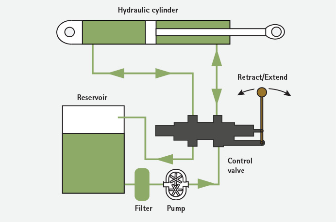
The path taken by hydraulic fluid is called a hydraulic circuit. For hydraulic fluid to do its work, it must flow through the pump,valves, hoses, and tool and then return to a reservoir. The fluid is then filtered, given a chance to cool, and repumped. Rescue tools typically have open center circuits, using pumps that supply a continuous flow. The flow is returned to the tank through the control valve’s open center—that is, when the control valve is centered, it provides an open return path to the tank.
Pumps create flow—not pressure—and pressure is a by-product of the hoses, valves, and so on. To illustrate this point, a pressure gauge attached to the discharge line reads the resistance to the pump’s flow. When the control valve is actuated, it routes fluid to and from an actuator and tank to the tool. The fluid’s pressure will rise to meet any resistance since the pump has a constant output. If the pressure rises too high, fluid returns to the tank through a pressure relief valve. (Note: For best operations, the hydraulic fluid temperature should remain between 60°F and 140°F. The reservoir has baffles in it to mix the hotter return with the cooler fluid contained.)
The hydraulic fluid is mostly incompressible, but it may contain up to 10 percent air. Pascal’s Law, which explains that a force or pressure on a small surface can be transferred to a larger surface, amplifying the force, describes the action that creates the mechanical advantage. Think of the small piston attached to the pump handle of a hydraulic bottle jack. The small force you create by pumping the small piston with the lever (handle) transmits the force [the pressure in pounds per square inch (psi)] to a larger area (the square inches in psi). Therefore, by simply pumping the jack by hand, you can lift several tons.
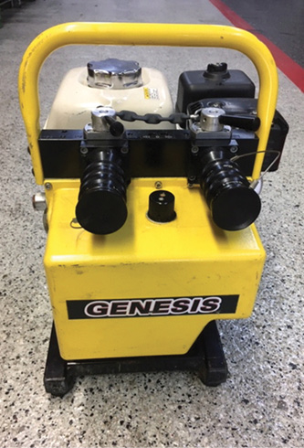
(1) The valves on this hydraulic power unit are set to the right so the pump will deliver high flow to that tool. It will work faster (a higher gpm), but it still flows at 10.5 psi. Read the manuals of your tool kit to learn the specifics of its correct operation. (Photos by author.)
As the tool is pressurized by the hydraulic circuit, pressure builds from the resistance of pushing against the workpiece, attempting to “pop” the door open. This type of hydraulic power system features a positive displacement pump, which means that if operators pump against a closed head for very long, the pressure will build until something relieves the strain. System operating pressure is directly related to the load applied; it’s ultimately relieved automatically by internal overpressure valves or by decreasing the load on the working end of the tool. The tool system will load up and build pressure until the object is displaced, the operator releases the tool, or the relief valve kicks in. These forces are great and can break the tool. For example; if vehicle hydraulic cutters are not centered properly and deep enough in the cut, the jaws can break off and have broken off.
Hydraulic Safety Issues
Following are some considerations when working with hydraulic tools:
- Pressures in hydraulic systems can be 2,000 to 10,500 psi. Always assume they’re under pressure.
- Treat working with them as “hot” work. Keep a fire extinguisher or charged hoseline nearby.
- Always wear proper personal protective equipment including bunker gear and hearing, hand, ear, and eye protection.
- When hoses are left in the hot sun or on hot pavement, the fluid will expand and prevent uncoupling. If that’s the case, relieve pressure back through the system.
- Inspect hoses for leaks and excessive wear, ensuring all fasteners are tight. Don’t use your hands to check for pinhole leaks; the pressurized fluid can penetrate skin.
- Hydraulic fluid injected under the skin is a VERY serious injury that can lead to the loss of the infected body part.
- Make sure fluid levels are full. Do not use any fluids other than those recommended by the manufacturer.
A small, four-cycle gasoline engine powers most hydraulic units. Keep fuel fresh and change filters at proper intervals. You can find specific starting instructions in the tool’s owner’s manual. However, the following steps work for most units:
- Check the fuel, the crank case oil, and hydraulic fluid levels.
- Make sure the ignition switch and fuel valve are on.
- Pull the choke out fully, pull the recoil starter cord, gently allow it to return once the engine is running, and return the choke to the open position.
- Start the engine/pump with the dump valve open so the gas engine has no load on it during startup.
- Once the engine is running, move the hydraulic dump valve to power the tool and cycle the tool valve to purge air. Also, open the dump valve when changing out tools unless you have the “hot disconnect” couplings.
Note: Knowing when to change hydraulic fluid is similar to car engine oil; it is a matter of duty cycle. Heat and age break down the fluids. Most manufacturers’ fluids will undergo a color change when their fluid needs changing. Keep spare fluid with you for the occasional top-offs, and check for color change. The fluid rarely gets “too dirty”; however, always wipe your couplings off before hooking them up.
Vehicle Rescue Hydraulic Systems
The load-sensing, two-stage, positive displacement pump can be powered by an electric motor or gasoline engine; they can be broken down further to two- or four-cycle gas and battery engines. Vehicle rescue tools are hydraulic jacks with different tools bolted on. The fluid is pumped into the pressure line; travels through valves, couplings, and so on; reaches the rescue tool’s hydraulic cylinder; and extends into the cylinder operating the cutter blades or leverage arms of a spreader. The fluid then gets directed back to the reservoir through a hose called the “return line.” The hydraulic fluid tank is nonpressurized. Most tools are powered on extension and retraction and are called “two-way” cylinders. A one-way cylinder has power only on extension.
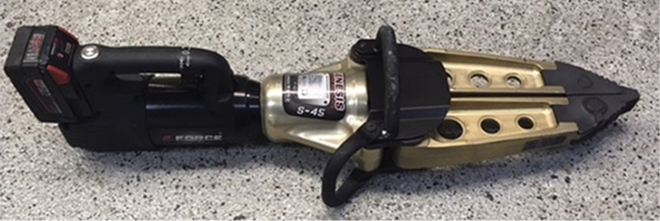
(2) This is a battery-powered tool, but it still turns a hydraulic pump. Check cutter blades on hydraulic shears on the big bolt at the pivot point and lube them after heavy use. Windshield glass can work into the pivot point/bolt and grind into the steel, damaging the cutter, so clean out this joint.
The two stages of the pump are high flow/low pressure and low flow/high pressure. The highest flow is around two gallons per minute (gpm), and the highest pressure is 10,500 psi (depending on the manufacturer). On startup, the motor/engine is operating the first-stage pump. When you engage to force a door or cut a post and the tool meets resistance, the pressure builds within the pump and the second stage kicks in. At this point, the tool operator must keep the tool valve open, which may take five to 10 seconds. This second stage then increases pressure to complete the push or cut.
Some hydraulic systems have valves you can set in a specific position to achieve high flow and high pressure on a specific tool for increased operation. Some power units may be able to operate two or more tools simultaneously, two tools intermittently, or just a single tool. Read your manual for your specific tool system. (Note: National Fire Protection Association 1936, Standard on Rescue Tools, recommends bench testing the pump pressure every year to make sure you have no seal or pressure problems.)

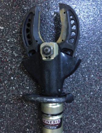
(3) When cutting a vehicle post with glass, keep the cutters oriented so they are resting on the post (easier to handle) and so the glass fragments drop away from the cutter and don’t get trapped in the rubber boot. After making a post cut, allow the cutter to swing down and tap the ground on the tips to knock some glass fragments out of the cutter. Glass is hard enough to damage the big bolt pivot point. You will need to retorque this bolt down after heavy use to keep it cutting properly.
Inspect hose and couplers for physical, thermal, and chemical damage. Check for any leaks; many can be fixed by simply tightening the threaded connections. Do not use the hydraulic hoses to lift, carry, or move any of these tools or power units. Take any hose with bulging or swelling out of service. Avoid sharp bends or kinks in hydraulic hoses. If you apply pressure to a bent or kinked hose, the flow restriction will cause a buildup in pressure, which may lead to damage of the hose lining and cause the hose to fail; the system is protected with check and relief valves that minimize this. Clean hoses and couplers with soap and water, wipe down, and air dry.
The hose couplings are going to leak, especially in hot weather. The film of hydraulic fluid on your compartment floor is likely a temperature-related leak. The hydraulic fluid expands when hot and will seep out of the coupler if trapped in a hose. To prevent this, keep them hooked together in a loop. Then, as the fluids expand and contract, it will circulate.
Figure 1. Generic Hydraulic Circuit for Rescue Tools
A common problem with some four-cycle engines is finding gasoline in the crank case. If there is a strong smell of gasoline when checking the oil/crank case level, it is because the gasoline will break the oil down and cause excessive wear on internal engine components. This usually means one of two things: If you have a fuel shutoff valve, someone likely forgot to close it after using the engine, or it isn’t closing properly. Shut the valve and pull the fuel line to see if it leaks. If it does, you may need a new valve. The other way this happens is if the needle valve in the carburetor float assembly is worn and allows fuel to leak. Once fixed, change the oil.
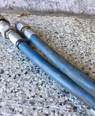
(4) The outer (blue) protective jacket of this hose is getting stretched and thinned out because of expansion of the inner core. This hose should be replaced.
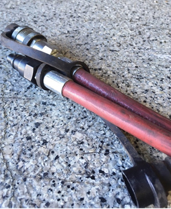
(5) The outer (red) protective jacket of this hydraulic hose shows no thinning or expansion of the inner cord. This is what your hose should look like.
Note: Regarding long-term gasoline storage, gasoline right out of the pump is typically safe for three to five months. If treated with a fuel stabilizer (one ounce in 10 gallons of gasoline, typically), you can expect six to eight months of good performance. What happens to the stored gasoline is many of the volatile compounds evaporate over time, leaving less octane. You can use stabilizers in a two-cycle mix, straight gasoline, marine fuels, diesel, and E85 (15 percent ethanol added). It limits this evaporation, but it won’t help much if you have water in the gas, which is another common issue. Most gasoline has ethanol added. Ethanol attracts and holds water, thins the fuel, corrodes the metal parts of our engine, and can freeze up. Gas-line antifreeze and water remover products bind with the water molecule, lessening these negative effects. If you are storing the engine long term, run the engine until dry with the treated fuel, drain any remaining gasoline into an approved container, and properly dispose of it as needed.
Hydraulic Tool Power Unit Troubleshooting
Following are some solutions to common issues you may face when working with hydraulic tools:
Problem: Engine fails to start or is hard to start.
Possible reasons/remedy:
- Out of gas—check the tank and fuel filter/line.
- Spark plug disconnected or faulty—check and replace; check the air filter and plug the gap; check the crank case oil level; the fuel valve is closed.
Problem: Engine overheats.
Possible reasons/remedy:
- Low oil level—check/add fill and check oil cooling radiator, if equipped.
- Airflow obstructed—always operate in a well-ventilated area unless the tool is electrically powered.
Problem: The tool is not operating.
Possible reasons/remedy:
- Low hydraulic fluid—check and refill if necessary, perform a pressure check, determine if it is the tool or power unit; check the gpm setting.
- Loose seals or coupling—check for obstructions or dirt, and clean and tighten as needed. If it still leaks, tag it as “out of service” and send it to a service center.
- Load is too heavy—reduce the load.
- Air is trapped in the system—cycle the tool full open and closed while keeping an eye on the fluid reservoir level; it may get too low as the air bleeds off as the fluid cycles through the system. Keep in mind that when your tool is fully extended or open, the fluid in the reservoir may appear low, but this is normal. When the unit is off and the tool is retracted, the fluid level should return to normal. If it doesn’t, fill as needed with the manufacturer’s recommended fluid.
Problem: The tool loses power.
Possible reasons/remedy:
- The relief valve is malfunctioning either through leakage, incorrect settings, or a broken valve spring.
- Air trapped in fluid—dirty fluid, clogged screen.
- Valves may be recirculating oil through the system—check the directional valve to ascertain the issue.
- Internal leaking in the valves or cylinders—check these components and their condition.
Figure 2. Hydraulic Force Torque
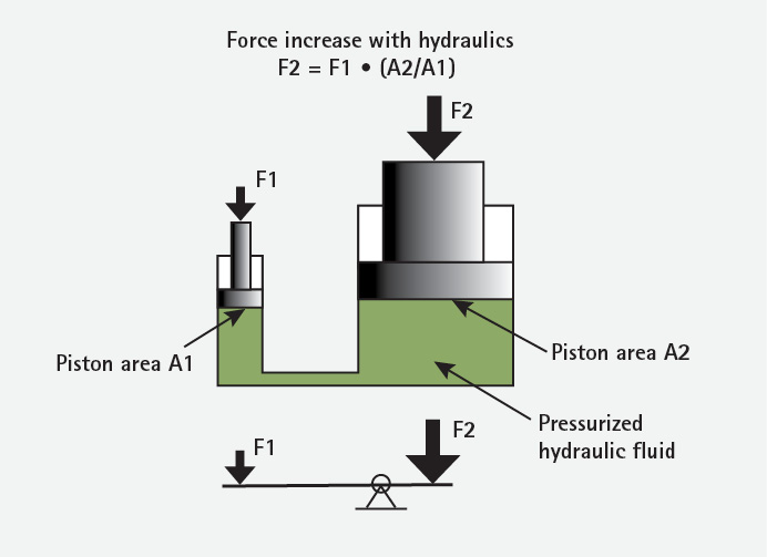
If F1=1 psi, then F2 =10 psi because A2 has 10 times more surface area than A1; this is the same principle that creates the lifting capacity for air bags. Hydraulic forces are amplified by Pascal’s Law. The smaller force exerted on the small piston of this bottle jack is increased when transferred to the larger surface area of the larger piston. The pressure increases because of the larger surface area of the larger piston.
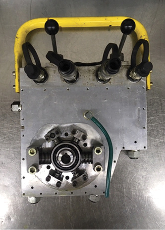
(6) The internal workings of a vehicle hydraulic pump system. Four low-pressure pumps (1, 5, 7, and 11 o’clock at 5,000 psi). The pumps located at 3 and 9 o’clock are for high pressure that, when backpressure rises with increased resistance (or if the door won’t pop), it is sensed and boosts pressure to 10,000 psi.
Are you ready to move beyond being a button pusher? By understanding the operating principles and how to keep these essential tools running, you will become a better operator and rescuer. Train and maintain these tools like someone’s life depends on them, because it does.
STEVE SHUPERT has 35 years in public service. He retired from Miami Valley (OH) Fire District and serves as a rescue team manager for Ohio Task Force #1 Federal Urban Search and Rescue. Shupert is also the chair of the FEMA Rescue Sub Group and the director of training for 501c3 Crash Course Village in Kettering, Ohio.

