
By Joseph R. Polenzani
The apparatus-mounted master stream (or deck gun) is a potent and versatile tool fire officers often overlook as a tactical option. For fires within its reach, there is arguably no faster way to deploy a fire stream than with a monitor that is already connected to the pump. Although we typically think of deck guns as a component of defensive operations, they have a role in offensive fire attack as well. The high-volume stream from a deck gun can be used to quickly knock down a large amount of fire, especially in smaller structures such as garages or mobile homes, or to temporarily darken down fires in difficult-to-reach areas including upper floors, eaves, or balconies to buy time to get offensive handlines in place (photo 1). However, regardless of the application, it is important that the pump operator deliver the correct flow.
In the fire service, our decision making is largely guided by past experience (“what worked last time should work this time”), a concept known as “Recognition Primed Decision Making.”1 In other words, if it has been my experience that a 1¾-inch handline flowing 180 gallons per minute (gpm) will safely extinguish two fully involved residential bedrooms, then I am likely to deploy that same line the next time I see the same type of fire. However, if I unknowingly send my fire attack crew into that house with a line flowing only 125 gpm, the results could be dangerously different.
The Deck Gun: The Forgotten Option, Part 1 | Part 2
The same is true with master streams. If an incident commander is counting on 600 gpm and the pump operator delivers only half of that, the results will not match the officer’s past experience. Therefore, it is critical that the pump operator consistently reproduce appropriate fire flows on demand.

(1) A blitz attack with a deck gun can quickly halt the forward progress of a visible fire, allowing time to get offensive handlines in place. (Photos courtesy of author.)
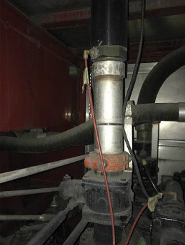
(2) The path that water takes from the pump to the deck gun. From bottom to top: pump discharge manifold, discharge control valve, and discharge pipe. The pressure tap is the brass-colored, right-angle fitting just above the joint between the silver and black vertical pipes. The red plastic hose transmits the water pressure to the gauge on the pump panel. On this pumper, the pressure tap for the deck gun is in a straight, large-diameter pipe directly below the base of the monitor, so the majority of the postgauge friction loss will be in the monitor.
In situations where water is limited, it’s even more vital that the pump operator manage water usage. For example, if an officer knows that his tanker shuttle operation can supply a maximum of 750 gpm, the pump operator needs to ensure that he operates within those limitations. This task becomes even more challenging when using a combination of master streams and handlines. Unfortunately, dedicated flowmeters for apparatus-mounted monitors are often viewed as an unnecessary expense, so pump operators, especially those using automatic nozzles, are frequently left to estimate their actual fire flow.
A case in point: During my last assignment as an engine company captain, our crew was issued a new automatic fog nozzle for our deck gun. Although we typically kept a set of stacked smooth bore tips and a stream shaper on the monitor, our department also issues each pumper a fog nozzle, which allows the company officer to select the appropriate tool for the task at hand. As with any new piece of equipment, we set aside some training time for that shift to become familiar with the nozzle’s operation and capabilities. At the time, my engine shared a house with a quint company. Their engineer (driver), Mike, was one of our department’s sharpest pump operators. He was my designated “think outside the box” guy, and his questions or observations would often spark an entire training session.
As we looked over the new nozzle, Mike asked an interesting question: “If this is an automatic nozzle, how do we know how much water we’re flowing? With our smooth bore and fixed-gallonage master stream nozzles, we know that we should get a certain gpm discharge at the proper nozzle pressure. However, this nozzle is rated 500 to 1,250 gpm with a 200 pound-per-square-inch (psi) maximum. What will our flow be at 80 psi?”
Now, at that time, our department had used automatic handline nozzles for more than 25 years, and our engineers were accustomed to the calculations required to achieve a variety of fire flows with both 1¾- and 2½-inch hose. However, common friction loss formulas for hose, such as CQ2L, and friction loss rules of thumb aren’t applicable when pumping to an apparatus-mounted monitor.
As we thought about it, however, we realized that by measuring the friction loss between the deck gun’s discharge gauge and a smooth bore nozzle’s tip at a variety of flows, we could use the same principles to calculate target flows for the automatic master stream nozzle. Once we had the theory figured out, the procedure was pretty straightforward. The only tool we needed was a handheld pitot gauge. Before moving on, though, let’s take a closer look at why this concept works.
Theory
Fixed-gallonage fog nozzles and smooth bore tips are designed to produce a given volume of water at a specified pressure. In the case of master stream nozzles, the standard pressure is 80 psi. Unfortunately, the deck gun discharge gauges on fire apparatus do not take their pressure readings at the tip or even at the base of the master stream nozzle. Instead, they read the pressure in the deck gun’s discharge pipe as it leaves the pump discharge manifold (photo 2). As a result, the pressure at the nozzle can be well below the one shown on the discharge gauge. The longer the discharge pipe is and the more bends it has, the greater the pressure loss will be (photo 3).
Master stream appliances also have a certain amount of built-in friction loss. One common deck gun model has an advertised friction loss range from 3 psi at 400 gpm up to 25 psi at 1,200 gpm. Other monitors have similar ratings. Both the piping and appliance losses must be factored into the calculations.
A fundamental rule of hydraulics is that friction loss increases with volume (flow). As the deck gun’s flow rate increases, so does the friction loss between the gauge’s pressure tap and the nozzle. For example, with a 1¼-inch smooth bore tip flowing 400 gpm, the tip pressure and the discharge gauge readings in our test were both 80 psi, which means there was almost no pressure loss between the discharge manifold and the nozzle. However, a 1¾-inch smooth bore tip flowing 800 gpm required 95 psi on the discharge gauge to maintain 80 psi at the nozzle, which indicated a loss of 15 psi in the pipe and appliance. By measuring this pressure differential at various standard flow rates, we can determine the proper pump discharge pressure (PDP) needed to deliver 80 psi at the nozzle tip regardless of nozzle type. So, how do we go about doing all this?
Procedure
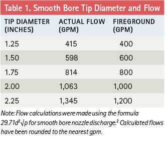
Step 1: Determine the desired target flows. If your department uses stacked smooth bore tips on its master streams, the diameter and gpm rating of the tips will determine your target flows. If your department carries only automatic or fixed-gallonage fog nozzles, you will have to obtain a set of smooth bore tips whose gpm ratings are within the minimum and maximum capabilities of your fog nozzle and use the flows provided by those tips as benchmarks. In either case, it’s important to know the limitations of your apparatus’s pump and monitor, as there’s no point in trying to obtain a 1,200-gpm flow from the deck gun if the truck has only a 1,000-gpm pump. Conversely, a pumper with a 2,000-gpm pump will not be able to discharge its entire capacity through a standard monitor and nozzle. The most common master stream smooth bore tip sizes and their flows are shown in Table 1. The numbers in the Fireground column are the easy-to-remember field values.
Step 2: Establish an adequate water supply. For these tests, you will be flowing up to 1,200 gpm, so the water supply needs to be able to deliver that volume throughout the entire testing period.
Step 3: Select the appropriate tip and mount it on the deck gun. In our case, it was easiest to work from the smallest flow to the largest, so we started with the 1¼-inch tip. Note: If you always use a stream shaper with your master stream nozzles, then it’s important that it is also in place during testing. If your apparatus has an extending monitor (one that can be elevated from its stored position), conduct the test with the monitor in its most commonly used configuration. Our testing found no measurable difference with the monitor in the raised or lowered position, but your results may vary.
Step 4: Increase the pump’s revolutions per minute (rpm) until the deck gun’s discharge gauge reads 80 psi. This will be your starting point for taking measurements.
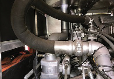
(3) On this pumper, the two right-angle turns in the deck gun’s pipe between the discharge manifold and the base of the monitor will increase the friction loss. The pressure sensor is visible on the left side of the pipe, just above the discharge control valve.
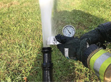
(4) A firefighter uses a pitot gauge to measure the discharge pressure of a smooth bore nozzle. By comparing the nozzle pressure to the reading on the discharge gauge, pump operators can determine the amount of friction loss that must be accounted for when calculating a proper pump discharge pressure.
Step 5: Measure the stream’s discharge pressure at the nozzle tip, using the pitot gauge. Pitot gauges measure the pressure of the water as it exits the tip of the nozzle, so it is important to use a consistent technique when taking each pressure reading. Consult the manufacturer’s instructions for the proper use of your gauge. However, if instructions are not available, the steps below present a good general guideline:
- Open the pitot’s drain petcock and verify that the gauge reads 0 psi.
- Place the pitot’s blade into the stream, with the blade perpendicular to the nozzle’s orifice and the blade’s opening centered in the stream. The distance between the edge of the blade and the nozzle orifice should be equal to one-half of the nozzle diameter. For example, on a 1½-inch tip, the blade should be ¾ inch from the opening (photo 4).
- Once water is running out of the gauge’s drain, close the petcock and observe the reading on the gauge. Depending on the configuration of your apparatus, it may be easiest to have one person hold the pitot in place while a second person operates the petcock and takes the pressure readings.
Step 6: Continue to slowly increase the pump’s rpm until the pitot gauge reads the desired nozzle pressure (80 psi).
Step 7: Note the pressure shown on the deck gun’s discharge gauge. By subtracting the nozzle pressure (80 psi) from the reading on the discharge gauge, you will be able to determine the amount of pressure lost between the gauge and the nozzle for the current flow rate.
Step 8: Repeat the above process for each tip size and flow rate.
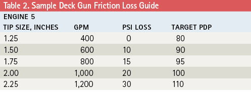
Once you have taken measurements for each target flow, the results can be made into a table, similar to Table 2, and placed on the apparatus for reference. On our chart, we elected to list the nozzle sizes in decimal format instead of fractions, as that’s how our tips were stamped. If your tips are marked with fractions (e.g.,“1¾”), you may choose to use those on the table instead.
The fireground is a complex and dynamic environment where multiple coordinated and interconnected actions are required for success. Although we rely on past experiences to guide our decisions, each fire scene is unique. Often, the only consistency from incident to incident can be found in the tactics, techniques, and equipment we bring with us. All of this makes it that much more important that we are able to perform in a predictable and professional way. As a pump operator, you should always know your role, know your equipment, and know your flow.
Endnotes
1. For more information about Recognition Primed Decision Making, see “Fireground Command Decisions,” Barry Bouwsema, Fire Engineering, March 2007; https://emberly.fireengineering.com/articles/2007/03/fireground-command-decisions.html.
2. The full formula for calculating flow through an orifice (such as a smooth bore nozzle) is acdd2√p, where “a” is a constant, “cd” is the coefficient of discharge, “d” is the orifice diameter measured in inches, and “p” is the pressure at the orifice (nozzle tip). Because the cd value for smooth bore nozzles is typically so close to 1 (0.96 – 0.997), most “fireground” formulas omit the coefficient of discharge from the equation. Civil Engineer John R. Freeman calculated the value of “a” as 29.71 in 1888; the “Freeman Formula” (29.71d2√p) is still in widespread use today. However, other values for “a” are also found throughout the fire service. Examples include 29.83 (American Insurance Association), 29.84 (National Fire Protection Association’s Fire Protection Handbook), and the abbreviated 29.7 version used by IFSTA and Jones & Bartlett.
JOSEPH R. POLENZANI began his career 27 years ago as a volunteer with the Ashland City (TN) Fire Department. In 1998, he became a career firefighter with the Franklin (TN) Fire Department, where he is a battalion chief. He also serves as a volunteer firefighter/engineer with the Williamson County (TN) Rescue Squad. He has a bachelor’s degree in fire administration, and is a fire officer IV, fire instructor II, safety officer, and apparatus operator. He has presented at FDIC International and has written for Fire Engineering.

