
By Bill Gustin
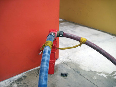
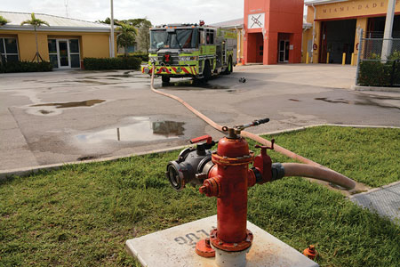
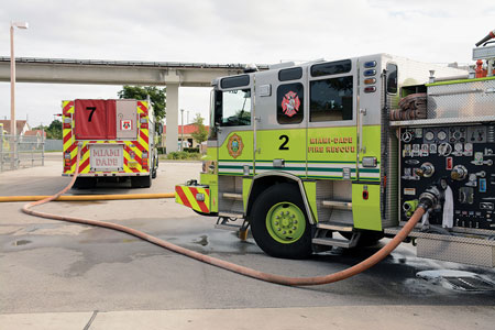
This article examines how a four-way valve and a “water thief manifold” give firefighters more options when operating with large-diameter hose (LDH). Many fire departments deploy their LDH as if it were a very long suction hose: The hose is laid from a hydrant to the fire scene-a forward lay-and connected directly to the “steamer” outlet of the hydrant by means of a 4½-inch thread to the Storz adapter. The hose is connected to an intake of an apparatus with a similar Storz-to-thread adapter or to a Storz fitting on an LDH intake valve connected to the pump’s threaded steamer connection. This arrangement is fine as long as the demand for water does not exceed the flow capability of the supply line. The limiting factors are the friction loss in the supply line, which is determined by its gallons-per-minute (gpm) flow, its length, and the hydrant’s pressure (photo 1).
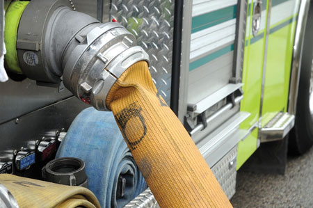 |
| (1) An LDH supply line connected directly to a hydrant collapses at the pump intake because of insufficient pressure. (Photos, except photo 21, by Eric Goodman.) |
The water supply systems in some areas are capable of flowing large volumes of water from large-diameter water mains but at relatively low pressures. Consequently, the water is available, but the system lacks sufficient pressure to overcome the friction loss in a supply line to get it to the fire. This is one reason fire departments have criteria for when an LDH supply line must be pumped by an apparatus positioned at the hydrant, such as at fires in commercial occupancies, which may demand a large volume of water, or when a supply line exceeds a certain length.
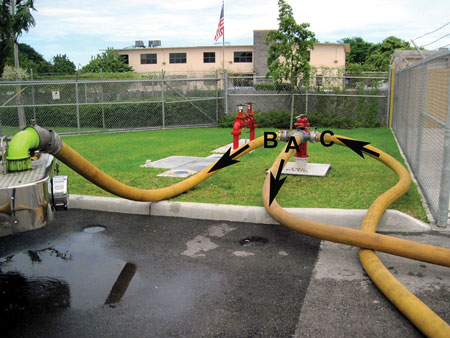 |
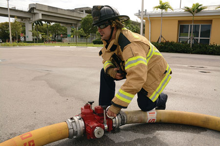
| (2) The four-way valve in operation has a 4½-inch threaded inlet with extended lugs that connects to the hydrant’s steamer connection. The five-inch LDH supply line to the fire is initially supplied with only hydrant pressure from outlet A; arrows indicate the flow of water. A later-arriving engine connects a 15- to 25-foot section of five-inch hose between outlet B and the intake of its pump-in this case, a front suction connection. Moving the valve handle to the position seen in the photo allows water to flow from the hydrant to the supply line and the intake of the pressurizing engine. Connecting another short section of five-inch hose from a pump discharge to inlet C pressurizes the supply line. |
There are three ways an engine company can pressurize a supply line laid between a hydrant and a fire scene:
- Perform a “reverse” hoselay from the fire to a hydrant (examined later in this article).
- Operate with two engines. One engine forward lays a supply line from a hydrant to the fire, and a second engine pumps the supply line at the hydrant.
- Pressurize a supply line by means of a four-way valve.
A four-way valve enables a pumping apparatus to lay a supply line from a hydrant and supply itself at the fire scene. If friction loss in the supply line caused by the gpm demand or the length of the hoselay results in an inadequate flow, a subsequent-arriving apparatus can receive water from the four-way valve and raise the pressure in the supply line without interrupting the flow of water (photo 2).
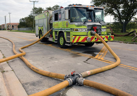 |
| (3) An engine boosts pressure in a relay pumping operation by tapping into a four-way valve connected in a long supply hoseline. |
Keep in mind that a four-way valve cannot make water that a hydrant is not capable of delivering, but it allows a subsequent-arriving engine to pump the supply line at a pressure that can significantly exceed the hydrant’s residual pressure. A four-way valve is ideal for a small department that may have to operate with just one pumping apparatus for a while before the arrival of additional apparatus. Also, it could be a valuable asset for departments that use supply lines smaller than five inches to overcome their higher friction loss.
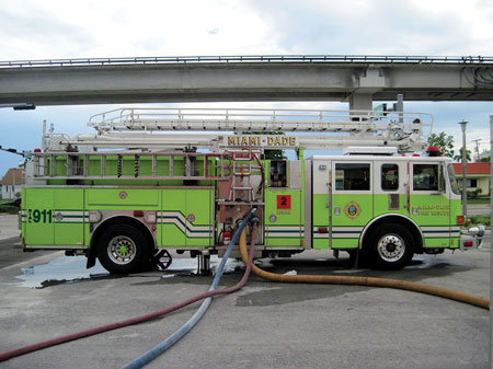 |
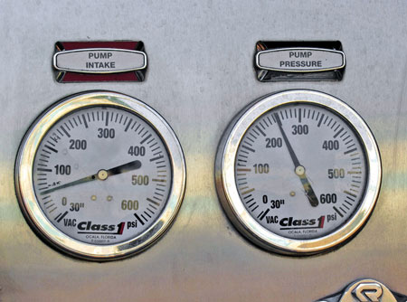
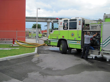
| (4-6) This apparatus is pumping two three-inch hoselines to a standpipe system FDC. It is supplied with 100 feet of five-inch hose connected to a hydrant with a four-way valve and is pumping at a pump discharge pressure of 250 psi with a residual pressure of 50 psi. |
A four-way valve can also be connected in a long supply line so that a later-arriving engine can be connected “inline” in a relay pumping operation without interrupting the flow of water (photo 3). For example, two engine companies empty their hosebeds to lay 2,000 feet of five-inch hose and connect a four-way valve near the midpoint of the hoselay with a Storz-to-4½-inch male thread adapter.
 |
| (4-6) This apparatus is pumping two three-inch hoselines to a standpipe system FDC. It is supplied with 100 feet of five-inch hose connected to a hydrant with a four-way valve and is pumping at a pump discharge pressure of 250 psi with a residual pressure of 50 psi. |
Supplying standpipe fire department connections (FDCs) with engines equipped with single-stage pumps may require a tandem pumping operation involving two pumpers to develop the required pressure.1 For example, if the fire pumps in a 70-story building were to fail, FDCs would have to be pressurized to as much as 500 pounds per square inch (psi) or more to overcome the pressure loss caused by elevation, overcome friction loss in the standpipe system, and provide adequate pressure for hoselines. To develop such high pressures, an engine connected to a hydrant pumps into the intake of the engine pumping the FDC, which raises its intake and discharge pressure. There are various methods for performing tandem pumping, which is essentially a very short relay because the engines are no farther than 100 feet apart. My department has devised a method that uses a four-way valve and large-diameter supply hose. The four-way valve facilitates the connection of a second engine to boost the intake pressure of an engine pumping an FDC.
 |
| (4-6) This apparatus is pumping two three-inch hoselines to a standpipe system FDC. It is supplied with 100 feet of five-inch hose connected to a hydrant with a four-way valve and is pumping at a pump discharge pressure of 250 psi with a residual pressure of 50 psi. |
If an apparatus pumping an FDC is not capable of developing the required pressure, a second apparatus is connected to the four-way valve at the hydrant and pressurizes the supply line to the engine pumping the FDC to a maximum pressure of 185 psi, the maximum allowable pressure for large-diameter supply line.
 |
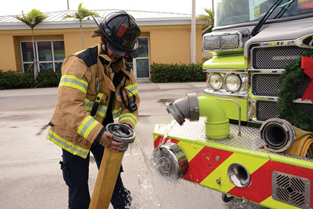
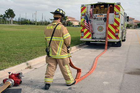
| (7) A second engine pressurizes the four-way valve at 185 psi. |
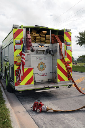
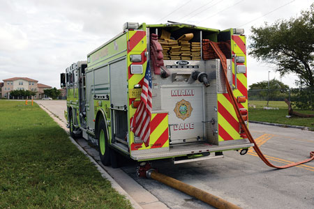
Let’s look at the following scenario as an example. An apparatus supplied by 100 feet of five-inch hose connected to a hydrant with a four-way valve pumps two three-inch hoselines to an FDC (photos 4-5). Its master pressure gauge indicates a pump discharge pressure of 250 psi, and its master intake gauge indicates a residual pressure of 50 psi (photo 6). An engine connects to the four-way valve and pressurizes the supply line to 185 psi (photo 7). This raises the residual intake pressure of the apparatus supplying the FDC to 170 psi and increases its pump discharge pressure to 400 psi (photo 8). It’s important to note that this increase in pressure was achieved without increasing its engine revolutions per minute (rpm).
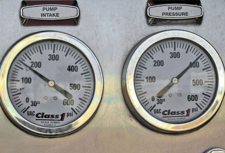 |
| (8) This raises the discharge pressure of the engine pumping the FDC to 400 psi and its residual pressure to 170 psi with no change in its engine rpm. |
Say the apparatus pumping the FDC receives 150 psi, as shown on its master intake gauge; in this case, it would have to develop an additional net pump pressure of 350 psi to reach the required pump discharge pressure of 500 psi. Keep in mind that a limiting factor in this operation can be the setting of intake relief valves, which may open and dump water below the desired intake pressure.
 |
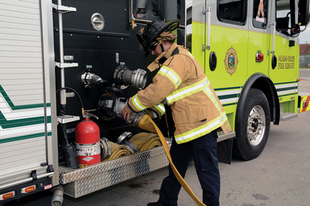
| (9) This engine is supplied by three-inch hose. The four-way valve is connected to the hydrant and used as a gate valve in case a steamer connection is later necessary. |
Four-Way Valve as a Gate Valve, Elbow, or Wye
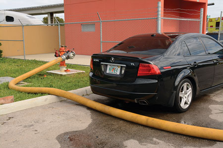 |
| (10) A four-way valve improvises as an elbow to reroute the supply line around the vehicle blocking the hydrant. |
A four-way valve can be improvised as a gate valve in two scenarios. First, let’s say that an engine company arrives at a fire in a small private dwelling with a hydrant within one or two lengths of three-inch hose. In this situation, engine companies in my battalion have the option of supplying their apparatus with three-inch hose connected to one of the hydrant’s 2½-inch outlets (photo 9), but they must connect a four-way valve to the hydrant’s 4½-inch steamer connection and move its valve handle to the closed position. This allows connection to the steamer outlet if unforeseen circumstances arise without having to shut down the hydrant.
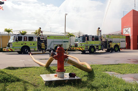 |
| (11) A four-way valve improvised as a wye is supplying two engines by flowing their deck guns. Both engines are flowing 600 gpm from 1½-inch smooth bore tips. |
The second scenario in which a four-way valve makes a handy gate valve is when a driver-engineer, by himself, must hand-stretch a supply line to a distant hydrant and stretching the five-inch hose would be physically impossible. The engineer may be able to stretch 2½- or three-inch hose to a hydrant, connect it to a 2½-inch outlet, and connect the four-way valve to its steamer connection. This would allow a later-arriving company to connect to it without shutting down the hydrant.
 |
| (12) The first-arriving engine lays in a five-inch supply line and supplies itself with three-inch hose, leaving the manifold’s large-diameter connection available for the later-arriving aerial apparatus. |
The following scenario raises the question, why didn’t the company lay in a supply line and establish its own water supply in the first place? There’s no argument here. A consequence of the common practice of permitting the first-arriving engine to operate from its booster tank and rely on a second engine to lay a supply line is that the latter engine may be delayed because of traffic, a train, or a drawbridge or may never get there because of an accident or a mechanical breakdown.
 |
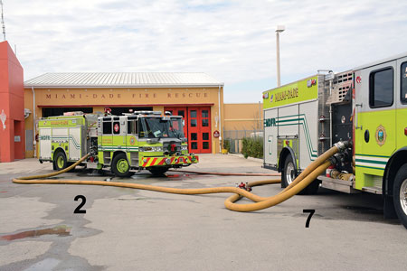
| (13) Engine 2 breaks down. Engine 7 pressurizes Engine 2 as if it were a big manifold to restore pressure to Engine 2’s hoselines. |
A four-way valve can also be improvised as an elbow when an illegally parked vehicle blocks a hydrant’s steamer connection (photo 10), or it can be used as a wye to supply two engines (photo 11). Admittedly, this is not an ideal arrangement because it limits the flow to both engines, but it is expedient when 2½-inch-to-Storz adapters are not available to supply a second engine from a hydrant’s 2½-inch outlet. My department supplied two engines in this manner at fires in large scrap yards and trailer parks where two engines had to operate remotely, each flowing no more than 500 gpm, and only one hydrant was available. The success of this arrangement depends heavily on a relatively high hydrant pressure to overcome the friction loss in the four-way valve and supply lines.
 |
| (14) The supply line to Engine 2 is shut off at the manifold. |
My department uses a water thief manifold primarily in a forward (hydrant-to-fire) hoselay. When an apparatus lays a five-inch supply line to itself or to a first-arriving company operating from its booster tank, the company laying the line will break the supply line, in 100-foot sections, at the coupling closest to its apparatus and connect the manifold. The manifold serves as a hose clamp, allowing the hydrant position firefighter to “send the water” without having to wait for the engineer to connect the supply line into the apparatus intake, which requires a short (15-, 25-, or 50-foot) section of LDH. This frees the hydrant firefighter to attend to other tasks.
 |
| (15) The supply line to Engine 2 is disconnected. |
The water thief manifold increases the versatility of LDH at large fires when the first-arriving apparatus is an engine and the fire is clearly a defensive operation requiring the operation of an elevated master stream. In this case, the engine can lay in its supply line, attach the manifold, and use three-inch hose from the manifold to its intake. This can provide sufficient water to operate handlines to protect exposures and leaves the five-inch outlet of the manifold available for a later-arriving aerial apparatus (photo 12). The manifold allows firefighters to control the flow of the supply line without having to run hundreds of feet back to the hydrant to shut it down.
 |
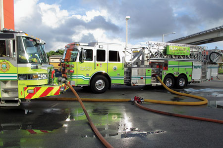
| (16) The supply line is reconnected to Engine 7. |
Consider these scenarios: An apparatus has to be relocated because of a potential collapse, exposure to fire, or to operate from a more effective position. In this case, firefighters can shut off their supply line at the manifold, move their apparatus, and reconnect and restore the flow. In photo 13, Engine 2 is pumping at the fire scene and suddenly breaks down. Engine 7 immediately connects a section of three-inch hose and pressurizes Engine 2 with its tank water to restore pressure to its hoselines as if the disabled apparatus were a large manifold. In photo 14, the supply line to Engine 2 is shut off at the manifold, disconnected from the disabled Engine 2 (photo 15), and reconnected to Engine 7 (photo 16). In photo 14, the supply line to Engine 2 is shut off at the manifold; Engine 7 then supplies Engine 2 by connecting a short length of five-inch hose between its large-diameter discharge and Engine 2’s right-side steamer intake (photo 17). Again, as in tandem pumping, this operation can be unsuccessful if Engine 2’s intake relief valves are set to open and dump water at a pressure below the discharge pressure needed for its hoselines.
 |
| (17) Engine 7 now supplies Engine 2 from its right-side, large-diameter discharge. |
Most of my department’s engines have split hosebeds of 1,000 feet of five-inch LDH and 600 feet of three-inch hose. Say that an apparatus laying a five-inch supply line from a hydrant to the fire runs out of hose before reaching the fire scene; in this case, the manifold would be connected to the end of the LDH (photo 18) and three-inch hose would be connected to one of its 2½-inch outlets using a double female adapter. The engine will then continue the lay with three-inch hose. A later-arriving company can lay in five-inch hose to or from the manifold to augment the water supply of the engine supplied with three-inch hose without interrupting the flow of water.
 |
| (18) This is the procedure to use if an engine laying an LDH supply line runs out of hose. The lay is completed with three-inch hose connected to the manifold. |
As mentioned, one way to supply LDH above hydrant pressure is to perform a reverse hoselay (from the fire to a hydrant), connect to it with one or more short sections of LDH, and pump the supply line from a large-diameter discharge. LDH can spoil a fire department and lull firefighters into a sense of complacency because it can adequately supply apparatus operating with just hydrant pressure at most fires. Apparatus that forward lay LDH to a fire can use preconnected hoselines and have all of their equipment readily available. Further, a quint apparatus can operate an elevated master stream, but there can be consequences. First, the fire scene can become congested with apparatus. At a large fire, engines can block the most strategic location for a later-arriving aerial apparatus. Second, as the demand for water increases, the residual pressure in water mains may become inadequate to supply hoselines with just hydrant pressure. At a large fire, extra-alarm engine companies should locate a hydrant, preferably on a large-diameter water main, and open it to ensure that it is in service and to flush rocks and sediment in the water main and “back down” to the fire scene. This positions the hosebed toward the fire and the apparatus in the direction of travel to the hydrant.
 |
| (19) Two portable master stream devices are connected to a manifold. |
When hydrants are distant and necessitate more than one hose load, call for another company to finish the hoselay. In photo 19, an engine company operates two portable master-stream devices connected to a manifold. All equipment was dropped at the fire scene before the engine began a reverse lay to a hydrant. The engine is connected directly to a hydrant with a short section of five-inch hose (photo 20). The four-way valve is used strictly as a 4½-inch × five-inch Storz adapter. The engine pumps the LDH supplying the manifold through its right-side, large-diameter discharge.
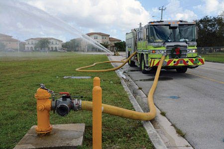 |
| (20) A short section of five-inch hose connects the engine to a hydrant. |
All Clark County (NV) Fire Department engines carry a manifold with inline gauges (photo 21) and use it to supply and control the flow of hoselines when members perform a reverse hoselay. Additionally, it is deployed in the courtyards of apartment complexes where a fire could be hundreds of feet away from an engine on the street or in a parking lot. The manifold, in effect, moves the engine’s pump panel to inside a courtyard.
![((21) Three 2½-inch hoselines are connected to this manifold with inline gauges, which are carried by the Clark County (NV) Fire Department. <i>[Photo courtesy of the Clark County (NV) Fire Department.]</i>](https://emberly.fireengineering.com/wp-content/uploads/2016/05/1605FE_GustinP21.jpg) |
| (21) Three 2½-inch hoselines are connected to this manifold with inline gauges, which are carried by the Clark County (NV) Fire Department. [Photo courtesy of the Clark County (NV) Fire Department.] |
Exercise caution when operating with a large-diameter water thief manifold. LDH does not tolerate slack or abrupt bends or twists, especially where it is connected to a manifold. Although manifolds are equipped with a relief valve, they can move violently if the LDH is charged too quickly. Our personnel are trained to keep a safe distance from a manifold when the LDH is being charged because it can break an ankle. Be extremely careful when charging LDH connected to a manifold that has Storz connections that do not swivel; a twist in the hose can cause the device to violently flip upside down. To make matters worse, one of the 2½-inch outlet valves can be knocked open, causing a “wild line.” Expect LDH to elongate and straighten itself when it is charged and the manifold to move. Try to keep at least 10 feet of hose straight behind the appliance (photos 22-23).
 |
| 22 A manifold is positioned too close to the apparatus, and there is slack and a bend in the hose. The manifold ends up under the apparatus when the supply line is charged. |
Endnote
 |
| 23 A manifold is positioned too close to the apparatus, and there is slack and a bend in the hose. The manifold ends up under the apparatus when the supply line is charged. |
1. See my article “Changes in High-Rise Buildings: Is It Time to Change Your Procedures?” Fire Engineering, April 2013.
BILL GUSTIN is a 42-year veteran of the fire service and a captain with the Miami-Dade (FL) Fire Rescue Department. He began his fire service career in the Chicago area and conducts firefighting training programs in the United States, Canada, and the Caribbean. He is a lead instructor in his department’s officer training program, is a marine firefighting instructor, and has conducted forcible entry training for local and federal law enforcement agencies. He is an editorial advisory board member for Fire Engineering and FDIC. He was a keynote speaker for FDIC 2011.
Fire Engineering Archives

