
BY RANDY NELSON
To ensure success at the pump panel, you can take just six simple steps. I was taught this incredibly simple and seemingly foolproof approach to pump operations as a young engineer in the United States Air Force. If you understand how each step affects pump operations, you can use the steps to troubleshoot most problems.
Generally, the six steps to be followed, in this order, are the following: 1. Engage the pump; 2. Water in; 3. Water out; 4. Calculate or determine pressure; 5. Throttle up; and 6. Set the relief valve. We will look at each step and discuss the issues you may encounter if you omit one of the steps or perform it incorrectly.
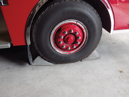 |
| (1) Always place wheel chocks when pumping. (Photos by author.) (2) Set the transmission selector in neutral; set the parking brake. |
Remember, you need to execute these steps in this order for most situations. Whenever you run into a problem, go back and start at step 1, ensure that you have performed each properly, and you will succeed. These steps have been very helpful in numerous situations in which I was pulled into somebody else’s pump problem. In that case, remember that it’s not your problem-you didn’t create the mess, so don’t let another’s mistake unsettle you. Simply start at step 1 and work your way through the process.
If needed, you can change the order of the steps to suit your apparatus. Some apparatus used in the petrochemical industry carry only foam and do not carry any water, so you would need to reverse the first two steps to “water in” first and then “engage the pump” to avoid running the pump dry.
Engage the Pump
You must follow your department’s specific standard operating procedures/guidelines (SOPs/SOGs) for such items as setting the wheel chocks-e.g., before or after engaging the pump (photo 1). Each apparatus may have distinct features such as an automatic or a standard transmission that will slightly change the process, but the procedure is the same. Here are the basic steps to ensure success of engaging the pump in most apparatus with an automatic transmission.
First, bring the apparatus to a complete stop, place the truck in neutral, and set the parking brake (photo 2).
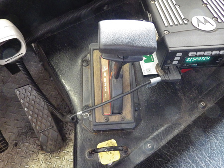 |
| (2) Set the transmission selector in neutral; set the parking brake. |
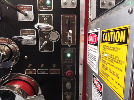
Next, while still covering the foot brake, activate or engage the pump shift. A green light may indicate the truck is ready to be shifted from road to pump gear, but you should also listen. You should be able to hear the pump shift activating (photo 3). It is imperative that an apparatus operator be in tune with his apparatus. Place the transmission in drive or in the appropriate gear for your vehicle. In an automatic, this will generally activate the fourth-gear lockup. If your apparatus is equipped with a standard transmission, select the correct gear, which is often fifth gear. Again, you may get another green light; more importantly, you should hear the pump engage. Do not let a burned-out, 30-cent light bulb dictate what your other senses tell you has successfully taken place.
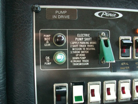 |
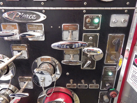
| (3) The pump shift with the “OK to Pump” light on. |
Another indication of positive shift into pump gear is the speedometer. In most apparatus, the speedometer will indicate a speed of between 10 and 15 miles per hour (mph). Again, this depends on the apparatus. On some apparatus, the speedometer pickup may be on the front wheels instead of the driveline, in which case you may not see the speedometer rise. After setting the parking brake and perhaps placing the wheel chocks, if the speedometer is indicating you are going 10-15 mph, it is a good indication the pump is engaged (photo 4). Look out the window to double-check. If you are sitting still, you are in business. Now you can exit the vehicle and set the wheel chocks, if your departmental procedures don’t require doing this before pump engagement.
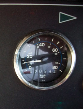 |
| (4) The speedometer indicates the apparatus is in pump mode. |
We still have a number of power takeoff (PTO) pumps that do not require putting the transmission in the drive gear. This is also true of some newer apparatus that pump when in neutral. Make sure you know what gear your apparatus pumps in. Also, when using an air-actuated pump transfer switch, a good rule of thumb is to pause just a second or two in the middle of the changeover to allow the gears in the automatic transmission to stop rotating instead of slamming the handle over in rapid-fire succession. Once you get to the pump panel, check the main pump pressure discharge gauge. If you usually run with a wet pump, you should see a slight pressure reading of between 20 and 30 pounds per square inch (psi). This is because the pump is turning and generating pressure, which is what you are reading on the discharge pressure gauge. This further confirms that you have placed the apparatus in pump.
Water In
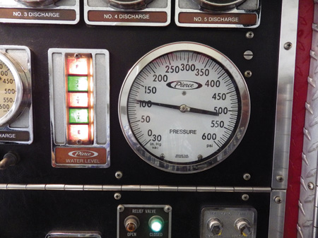
This is just as simple as it sounds-get water into your pump. Open the tank-to-pump valve or establish a water supply from a hydrant, a relay, or a draft (photo 5). Whatever the source, just make sure that you actually have water in the pump. If you normally run with your pump dry, you should now get a positive pressure indication on the discharge side of the pump, another indicator that you are in pump. If you are pumping from a pressurized water source, make sure the valve on the intake is opened fully. Now you should see a pressure reading on the intake side of the pump or compound gauge (photo 6). This is the static pressure from the positive-pressure water supply. If you were drafting, the intake gauge would read negative because you would be in vacuum. Without water in, you can’t get water out. Remember, pumps move water from one place to another. Pumps do not make water.
 |
| (5) Get water into the pump. |
It is important to make sure you are opening the correct valve. Years ago, I was pumping from one of our frontline engines that had two 2½-inch auxiliary inlets side by side. I got water from the hydrant and reached down and opened the inlet. I then shut down the tank-to-pump valve and quickly learned I had grabbed the wrong valve on the auxiliary inlets. I learned this when two very angry seasoned firefighters came to the engine to ask me what happened to their water. This could have been disastrous, but I was lucky and no real harm came from this mistake, except to my pride.
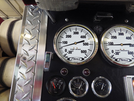 |
| (6) When operating from a positive pressure water supply, you should get an indication on the intake/compound gauge. |
Water Out
Select the appropriate discharge and open it (photos 7, 8). Notice I said, “select the appropriate discharge.” It seems apparatus manufacturers have a nasty habit of putting those darn discharge levers right next to each other, and in the heat of the moment it has proven to be far too easy to accidentally grab the wrong one. On one notable occasion, I was responding from home to a working structure fire in a mixed-occupancy commercial building on the ground floor with a boarding house above. As I approached, I was summoned, putting it very politely, to the pump panel of the first-due engine. They had deployed a 2½-inch preconnect to the rear door and the guy at the pump panel was frantically exclaiming to me that he couldn’t get water out of the pump. I jumped in and before I knew it, I was nearly as frustrated as he was. Then it hit me: Calm down, take inventory, and start at step 1. I checked each step and, lo and behold, he had simply opened the wrong discharge valve. Fortunately, it was to a capped discharge, not to one of the other preconnects (though in hindsight, that would have made the mistake clearly evident much sooner).
 |
 |
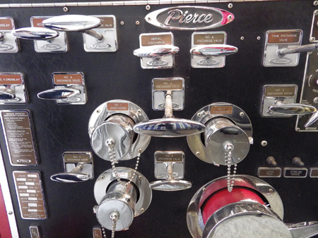
| (7, 8) Always ensure that the appropriate discharge has been opened. |
In another case, the officer kept telling the pump operator to give him water, but no water was coming out. The exasperated officer turned to another firefighter and asked if he could work the pump if needed. The young firefighter replied, “Yes, but maybe make sure the apparatus is actually in pump.” If the pump is not engaged, no water will come out (see step 1).
Many newer fire apparatus have color-coded levers on the pump panel corresponding to the color-coded label on the discharge. A quick check of the discharge will also confirm the correct discharge lever to open. Caution: Check to ensure that the labeling is correct. No one is perfect, and the person who installed those color-coded labels may have had a bad day at the factory. Do this before you find the mistake on the fireground. An added safety precaution for the pump operator is to make sure the hose on a preconnected hoseline is completely pulled out of the hosebed before charging the hoseline. If a hose is connected to a normally unused discharge outlet, make sure the hose is properly connected. Once the water is flowing, make sure that drains and bleeder valves are shut. In one recent case, we found that the main pipe for two discharges on the officer’s side of the apparatus had cracked and most of the water was getting dumped on the street under the pumper.
Calculate or Determine Pressure
Do the math, check your cheat sheet, consult the pump chart, or look at the label your department may have placed on the discharge valve of the preconnected lines. In any case, pump the line at the correct pressure. There really is no excuse for not pumping lines at the required pressure. Too often I have heard comments like, “We pump everything at 150 psi.” You don’t have to be a math whiz and memorize a bunch of formulas; if your department uses pump charts or predetermined pressures, use them. However, someone needs to periodically check the math to reflect changes in hose construction, manufacturer, size, and other factors that can greatly affect your department’s friction loss. You may even consult the manufacturer to get the friction loss numbers. This is especially easy when replacing old and buying new hose. We have replaced all of our old hose with modern low-friction-loss hose, and there is a big difference in the friction loss we see now over our old hose. There is no reason to guess; it is not that hard to figure out the required pressure.
Throttle Up
Slowly bring the throttle up to the correct pressure (photo 9). If you are pumping multiple lines, throttle up to the highest pressure needed, and gate down your other discharges (photo 10). Note that I stated to throttle up slowly. I have witnessed lines bursting because an anxious engineer grabbed the emergency stop and yanked the throttle out, instantly pressurizing the line to more than 300 psi for a car fire that was frankly not very well involved.
 |
| (9) A manual throttle control. |
If using a pressure governor or similar system, choose the correct mode [i.e., pressure or revolutions per minute (rpm)], and adjust the system according to the manufacturer’s recommendations and department SOPs. If you are in the Pressure mode, the engine speed will throttle down when a hoseline is closed and increase when a hoseline is opened. The pump discharge pressure will remain constant, and the pump operator will adjust the individual hoseline pressures using the discharge valves for each hoseline. If you use the RPM mode, using the relief valve is imperative to protect against redirected pressure when a particular hoseline is closed. Also, remember to throttle down before trying to close your hoselines. Just as life is easier when the pressure is off, opening and closing hoselines is easier when the pressure is off.
 |
| (10) Throttle up slowly to the desired pressure. |
Set the Relief Valve
This step is critical to safely pumping at any emergency or training evolution if you are not using a pressure governor (photo 11). I have heard more than one person tell me that it was unnecessary or their department didn’t do that. If you are pumping more than one hoseline, nothing could be further from the truth. The purpose of the relief valve is to protect firefighters at the nozzle from sudden increases of pressure when other hoselines are shut. If you aren’t willing to take the time to make sure your crew is safe operating at the end of a line you are pumping to them, then you have no business being a pump operator.
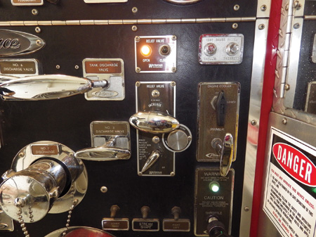 |
| (11) Always set the relief valve. |
The relief valve should be set approximately 10 psi higher than the pressure on the main pump discharge gauge. Relief valves are designed to operate within 30 psi and will operate sooner when larger volumes of water are being pumped.
Using this methodology has proven to be very effective. Remember, if you have a problem or get yourself into trouble, it is imperative to start from the beginning. Start at step 1 and ensure that each step has been completed in the proper sequence. With the help of some respected colleagues, we have taught this methodology for several years now. We have run it through the wringer; so far, we have yet to find a situation where we were not able to quickly find the problem.
Using these six steps in order each time you pump will prevent you from having issues. If you find yourself in one of those sticky situations in which you or someone else has made a mistake, take a breath, slow down, and go back to the beginning and double-check each step. I always think of the song lyrics by Brian Mcknight and Mark Wills: Anytime I have a problem, I “start back at 1.”
RANDY NELSON is 31-year veteran of the fire service, and served as chief of the East Alton (IL) Fire Department, which he joined in 1989. He began his career as a firefighter in the United States Air Force in 1984 and later was a firefighter for Olin Corporation. Nelson received numerous certifications, specializing in pump operations and apparatus. He has certifications in hazmat, technical rescue, and instructor I and II and is a certified fire officer and safety officer. Nelson has an associate degree in fire science (Lewis and Clark Community College) and a bachelor’s degree in fire service management and a master’s degree in fire service and homeland security management (both from Southern Illinois University, Carbondale). Since 2000, he has been an adjunct faculty member with Lewis and Clark Community College.
Tips from the Pump Panel
Every Pump Operator’s Basic Equation
IMPLEMENTING A PUMP OPERATOR TRAINING AND EVALUATION PROGRAM

