
By Brandon Burnett
What type of hose load does your fire department use for preconnected attack lines? Without conducting a formal research project, I would venture a guess that the majority of fire departments are using a flat load. Some departments use other hose loads such as the Minute Man, triple layer, Cleveland Load, and skid load; however, the flat load seems to be the default hose load for preconnected attack lines because of the ease of loading the hose load. Some departments place “pull loops” into the flat load to help deploy the flat load. The problem with the pull loops is that they have no purpose other than clearing the hose from the bed. This strategy is predisposed to creating a pile of hose (or a “pile of spaghetti”) next to the apparatus, which complicates the stretch. After using the flat load for years, I began to wonder if there was room for improvement.
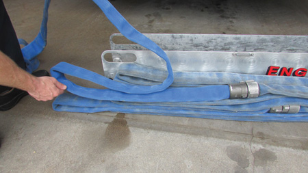 |
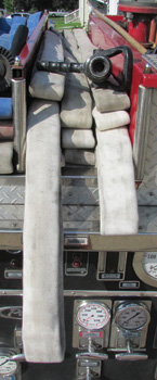
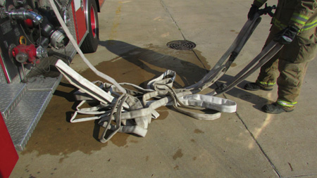
| (1) Load the hose in a flat load method until the next coupling, or 50 feet of hose, is in the hosebed. Make a loop on each side of the hosebed. This creates the nozzle firefighter loop. (Photos 1-3 by author.) |
When I stretch for initial fire attack, I prefer to take the nozzle and first coupling to the point of entry. I deploy the flat load from the hosebed and locate the first coupling. Once I find the first coupling, I bring the coupling next to the nozzle; this allows for 50 feet of hose to be flaked and ready to enter the structure for fire attack. While between classroom sessions at FDIC 2015 International, I was brainstorming the idea of placing a loop at the first coupling (50 feet from the nozzle), which would allow the nozzle and first coupling to be pulled simultaneously. After returning to the firehouse from FDIC, I loaded the flat load with a loop placed at the first coupling and a second loop at the second coupling. After stretching the flat load with the strategically placed loops, I found the stretch was smooth and afforded an easily flaked attack line.
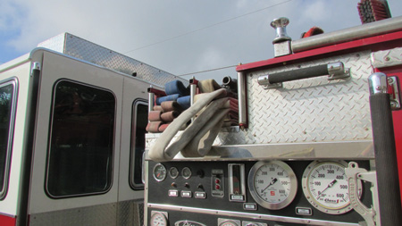 |
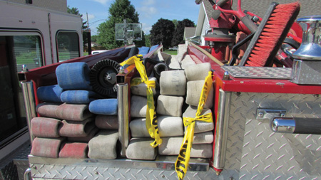
| (2) This is the finished flat load with strategically placed loops. Note that the backup loop is under the nozzle firefighter loop and the location of the nozzle. |
Loading the Hose
This flat load has strategically placed loops that allow the nozzle and backup firefighters to identify each 50-foot section of the hose. This load can be used with any length or diameter of preconnected attack line. A couple of variations need to be addressed based on the width of the hosebed. This hose load can be used with any type of hosebed or tray including mid-mounted crosslays (as depicted in the photos), front-mounted crosslays, or a rear hosebed.
Hosebed or Tray Can Accept One or Two Widths of Hose
For this load, use 150 feet of 1¾-inch fire hose with couplings every 50 feet. Start loading the hose as a flat load in the hosebed or tray. Once the first 50 feet of hose is loaded and the coupling is at the hosebed, make a single loop on each side of the bed; this creates the backup firefighter loop. We loaded this on the apparatus bay floor because it was easier to visualize outside of the hose tray. Once the backup firefighter loop is made, continue to load the hose in a flat load method until the next coupling (or 50 feet of hose is loaded into the bed). At this point, make another single loop on each side of the hosebed; this is the nozzle firefighter’s loop.
 |
 |
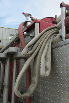
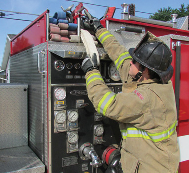
| (3) This is the opposite side of the hose load depicted in photo 2. (4) A third loop is added to allow the firefighter to locate the nozzle before pulling the strategically placed loops. (Photo by Josh Graham.) | |
We found that it was easier to place the loops on top of each other so that the nozzle firefighter knows that the top loop goes with the nozzle. After the nozzle firefighter loop is completed, continue to load the hose in a flat load method until all of the hose is loaded (photo 2). In photo 2, the nozzle is near the edge of the crosslay bed, allowing the firefighter to quickly locate the nozzle. When using a crosslay that is mounted high on the apparatus or if the firefighter cannot easily locate the nozzle, you can add a third loop to the side opposite the nozzle to allow the firefighter to identify the last fold that terminates with the nozzle (photo 3). This extra loop allows the firefighter to easily pull down the nozzle before deploying the hose load (photo 4).
Hosebed or Tray Can Accept Three or More Widths of Hose
When using a hosebed or tray that can accept three or more widths of hose, you most likely will not be able to place the loops on top of each other as in the above paragraph. We found it easier to load the hose as above but to make the first loop (the backup firefighter loop) significantly smaller than the nozzle firefighter loop (photo 5). This visual clue will allow the nozzle firefighter to take the larger loop with the nozzle and proceed to the point of entry. The backup firefighter will pull the smaller loop to complete the stretch.
 |
(5) When using a hosebed or tray that accepts three or more widths of hose, the nozzle loop is made larger than the backup firefighter loop, which allows the firefighter to easily select the correct loop. (Photo by author.) |
Other Considerations
If using 200 feet of preconnected hoseline, you can place the loops in various locations within the load. In one evolution, we placed the nozzle firefighter loop at the first coupling (50 feet) and the backup firefighter loop at the second coupling (100 feet). This load had 100 feet of flat load remaining under the backup firefighter loop in the hosebed.
Another option is to place the nozzle firefighter loop 75 feet from the nozzle (halfway between the first and second couplings). The backup firefighter loop was placed 75 feet behind the nozzle firefighter loop (halfway between the second and third couplings). The nozzle firefighter loop would still be deployed with the nozzle and taken to the point of entry, thus creating a flaked section of 75 feet that is ready for entry. Decide the distance from the nozzle to the loop after trying both 50 and 75 feet; the decision will depend on the needs of the fire company.
 |
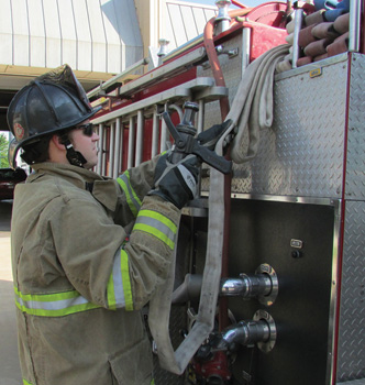
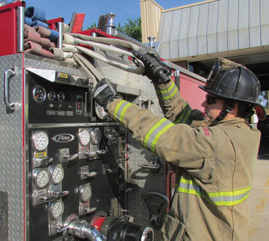
| (6) For two-firefighter deployment, the nozzle firefighter grasps only the nozzle and nozzle firefighter loop. (Photo by Josh Graham.) |
If using 100-foot sections of 1¾-inch fire hose, load the hose based on the length desired for loop placement rather than coupling location. For example, if you determine that the nozzle firefighter loop works best for your department at 50 feet from the nozzle, place the loop at 50 feet from the nozzle; there will not be a coupling at this length in the hose. The same would be true if placing a loop 75 feet from the nozzle-there will not be a coupling 75 feet or 150 feet from the nozzle.
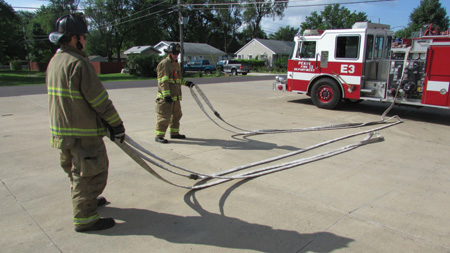 |
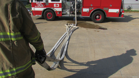
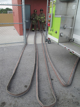
| (7) As the nozzle firefighter stretches the attack hoseline, the backup firefighter has pulled the backup firefighter loop and is stretching the remaining hose. The “preflaking” can be seen here. (Photo by Josh Graham.) |
Deployment
One or two firefighters can deploy this flat load with strategically placed hoops. The preferred method is the two-firefighter deployment, but based on personnel and incident priorities, a single-firefighter deployment may be necessary. Both methods are discussed below.
 |
| (8) When making the single-firefighter stretch, the firefighter grasps the nozzle and nozzle loop in one hand while grasping the backup firefighter loop with the other hand. (Photos 8-11 by Josh Graham.) |
Two-Firefighter Deployment Method
- Nozzle Firefighter Position. The nozzle firefighter will grasp both the nozzle and nozzle loop (photo 6). The firefighter will not place the nozzle or loop on the ground until he reaches the point of entry. As the firefighter pulls the nozzle and nozzle loop from the bed, the hose begins to “preflake” itself on the ground. As the firefighter reaches the point of entry, the nozzle and loop are placed on the ground together. The nozzle firefighter should assess whether any additional flaking is needed. We found that if flaking was needed, it was minimal compared to the amount of flaking needed when using a traditional flat load.
- Backup Firefighter Position. The backup firefighter (or engineer or officer, depending on your department) pulls the second loop. The backup firefighter grasps the second loop (backup firefighter loop) and begins to deploy the hose load behind the nozzle firefighter. If the stretch is longer than the remaining hose in the bed, which is based on the amount of hose under the backup loop (50 feet in our photos), stretch the backup firefighter loop in the direction of the point of entry and drop this loop when the hose is completely cleared from the hosebed (photo 7). If the stretch is shorter than the hose remaining under the backup firefighter loop (50 feet), stretch the backup loop to the point of entry with the nozzle firefighter loop. Once deployed and flaked, the attack hoseline is ready to be charged for the fire attack.
 |
| (9) When pulled from the hosebed with the single firefighter stretch, the hose will deploy into a “pile of spaghetti.” |
Single-Firefighter Deployment
With a three-firefighter engine company, the firefighter can deploy the attack line while the officer conducts the 360˚ walk-around/size-up and the driver/engineer prepares the apparatus for pumping operations. For this deployment, we used 150 feet of 1¾-inch fire hose. The nozzle firefighter grasps both the nozzle and the nozzle loop in one hand while grasping the backup firefighter loop with the other hand (photo 8). The firefighter then pulls the hose from the bed while maintaining the grasps on the nozzle and loops. In photo 9, the hose appears to become a “pile of spaghetti” as it is pulled from the hosebed, but the hose pulls cleanly from the pile as the firefighter stretches the hose, as seen in photo 10. The key to stretching the hose cleanly is to maintain grasps on the nozzle loop and the backup firefighter loop. If the stretch to the point of entry is less than 50 feet, the nozzle firefighter can take both loops to the point of entry (photo 11). When conducting a short stretch, you may need minimal flaking. If the stretch is longer than 50 feet to the point of entry, the firefighter should drop the backup firefighter loop once the hose is cleared from the hosebed. Once the backup firefighter loop is dropped, the nozzle firefighter then proceeds to the point of entry with the nozzle and the nozzle firefighter loop. The attack line is flaked, if necessary, and is ready to be charged.
 |
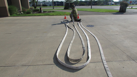
| (10) As long as the firefighter maintains the grasps on the loops and nozzle, the hose will stretch cleanly from the pile as the firefighter advances from the apparatus. |
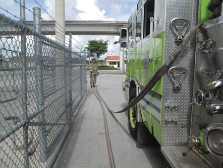
Close-Quarters Deployment
The flat load with strategically placed loops will easily deploy in situations that require “close quarters” maneuvers. This is important when the apparatus is parked along a fence, in an alleyway, on a congested street with parked vehicles, and in various other scenarios. When using the flat load with strategically placed loops in a close-quarters maneuver, the firefighter must consider the following:
- The nozzle and nozzle loop must be pulled in the direction of the point of entry, and the backup firefighter loop must be pulled in the opposite direction of the nozzle/nozzle loop (photos 12-13).
- When hose is pulled from the crosslay at a sharp 90˚ angle, any hose load is predisposed to “hanging up” when sharply pulled from the crosslay as the hose crosses the pump panel valves, hand rails, and other entanglement points. To help reduce the likelihood of “hang up,” position the apparatus operator/engineer at the pump panel to help facilitate the clearing of the hose from the crosslay during deployment. If the apparatus operator/engineer is not available to assist (or is assuming the backup firefighter position as the officer is conducting size-up), the deploying firefighters may need to place their respective loops on the ground and return to the apparatus to manually remove the remaining hose in the crosslay bed. The hose should be removed and placed on the ground parallel to the apparatus. Once all of the hose is cleared from the crosslay, the nozzle firefighter and backup firefighter can return to their respective loop and complete the stretch.
 |
| (11) When stretching to a point of entry that is less than 50 feet from the apparatus, stretch both the nozzle loop and backup loop to the point of entry. |
If a single firefighter must deploy the hose load in this situation, the firefighter should deploy the nozzle and the nozzle loop toward the point of entry first and then return to the apparatus and deploy the backup firefighter loop in the opposite direction.
The operation is reversed if the point of entry is to the front of the apparatus. The nozzle firefighter grasps the nozzle and the nozzle loop while the backup firefighter grasps the backup loop. The nozzle firefighter stretches toward the rear of the apparatus. The backup firefighter stretches the backup loop toward the front of the apparatus until the hose is completely cleared from the bed. The nozzle firefighter proceeds to the point of entry with the nozzle and the nozzle loop. The backup firefighter then proceeds with the backup loop to the point of entry. The backup firefighter continues to pull the backup loop to the point of entry and assists in flaking the line as he goes. Once the nozzle firefighter and backup firefighter have completed the stretch, the hoseline should be flaked and ready to be charged.
 |
| (12) The nozzle firefighter stretches toward the point of entry (the rear of the apparatus.) (Photos 12-14 by Eric Goodman.) |
Regular Flat Load Without the Strategically Placed Loops
If your department does not adopt the placement of the strategic loops within the flat load, this hose deployment method will still work with a regular flat load. Some departments are hesitant to change hose loads; following these steps will allow you to easily deploy the flat load even without the strategically placed loops. For example with a 150-foot preconnected hoseline, a firefighter should identify the location of the first coupling (50 feet) and second coupling (100 feet) from the nozzle. This can be accomplished by identifying different colors of the hose by looking at the hose load at the beginning of the shift or when the hose was loaded. The firefighter can make a mental note of the corresponding fold in the flat load and pull that fold when deploying the flat load.
 |
| (13) The backup firefighter stretches toward the front of the apparatus until the hose has cleared the bed. |
Another option would be to mark the folds that correspond to the couplings with chalk. In photo 15, the folds were marked with chalk and scene tape to facilitate visualization. To deploy the regular flat load, the nozzle firefighter should grasp the nozzle and the fold that corresponds to the section with the first coupling (50 feet from nozzle).
 |
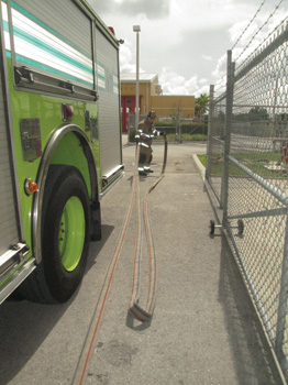
| (14) The completed “close-quarters” stretch. |
A single firefighter deployment is illustrated in photo 16. The firefighter grasps the nozzle and both folds as described in the above single-firefighter deployment paragraph. The firefighter then begins to pull the hose from the bed using the folds that correspond to the couplings. This will pull the flat load from the hosebed and into the “preflaked” position described in the preceding paragraphs. Once clear of the hosebed and minimally flaked, the attack hoseline should be ready to be charged for fire attack.
To deploy with two firefighters, the techniques are the same as described above other than that the nozzle firefighter grasps only the nozzle and the top fold that corresponds to the coupling that is 50 feet from the nozzle. The backup firefighter then pulls the other marked fold that corresponds to the second coupling (100 feet from the nozzle). Hopefully, your department will find value in adding the strategically placed loops in the flat load; if not, you can still make the deployment of the traditional flat load significantly easier.
 |
| (15) This hose deployment method will work with a standard flat load without strategically placed loops. The firefighter must locate the fold that corresponds to the first coupling (50 feet) from the nozzle. The nozzle loop is the higher marked fold. For this photo, the corresponding folds were marked with scene tape and chalk. (Photo by author.) |
In deploying this new variation of the flat load, we did not identify any issues that were detrimental to the deployment of the hose. The worst-case scenario would be that a firefighter forgets to use the strategically placed loops when stretching at a house fire at 3 a.m. The flat load with strategically placed loops is bidirectional and will pull off either side of the apparatus. No special techniques are needed, as the load can always be pulled as a regular flat load. The strategic loops are placed solely to make the stretch easier; they will not hinder deployment if they are not used. It is difficult to make changes in the fire service; however, this deployment technique will improve your fireground effectiveness. Reducing the time it takes to get water on the fire benefits everyone!
 |
| (16) For a single-firefighter deployment, the firefighter grasps the nozzle and marked folds as described. The firefighter is basically creating the strategically placed hoops when pulling the hose from the bed. The hose load is now deployed as previously described. (Photo by Josh Graham.) |
BRANDON BURNETT is a driver/engineer with the Pekin (IL) Fire Department. He has nearly 10 years of career experience, mostly as a member of an engine company. He is an Illinois instructor III, an advanced technician firefighter, a provisional fire officer I, a technical rescue technician, and a hazardous materials technician. He has an associate degree in fire science technology. He has taught within various disciplines including basic/advanced firefighter, technical rescue, and hazardous materials response.
Stretching and Advancing the Initial Handline
The Well-Hole Stretch
Hoseline Operations for Residential Fires

