
By MICHAEL CLARK and JOE SCAGLIONE
Every 84 seconds, a United States fire department is pressed into action. Our response? An aggressive fire attack. An aggressive interior attack is one of the most important fireground tasks we can employ to ensure that we successfully protect life and property while mitigating the incident. However, because of a number of dramatic fireground changes as well as research done by Underwriters Laboratories and the National Institute of Standards and Technology on the modern fire environment, we have had to rethink our approach. Budget cuts, staff reductions, and a lack of resources are realities for fire departments everywhere. Regardless, we are expected to complete our fireground objectives of saving and protecting life, preserving property, and effectively mitigating the situation.
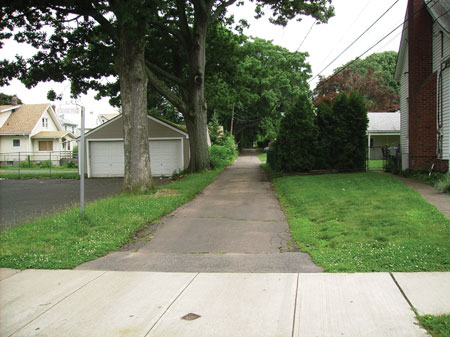 |
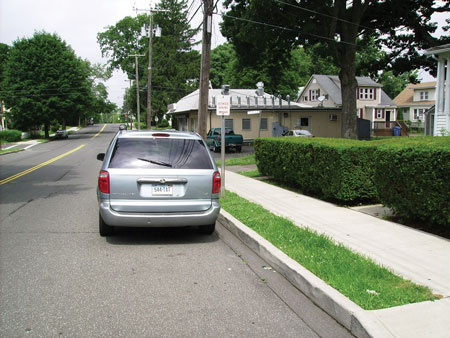
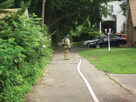
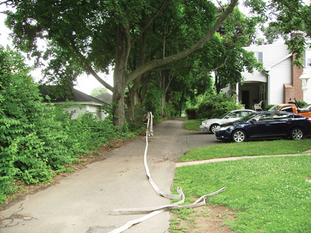
| (1) A typical “alley-like” street in Meriden, Connecticut. The house at the end of the road (not seen from the road) is more than 400 feet away. There are four homes on this street. (Photos 1-11 by Joe Scaglione.) |
Unfortunately, being asked to do more with what we have is our reality, and it is likely to remain that way for the foreseeable future. Getting the initial attack line in service quickly, safely, and efficiently is imperative to a successful fireground operation. As we have heard, “As the first line goes, so the fire goes.” Our solution is to overcome, adapt, and get the job done.
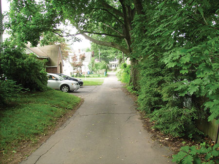 |
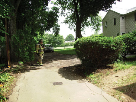
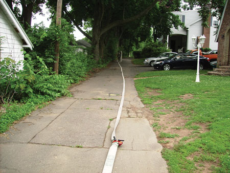
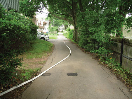
| (2) The view from the house to the street. The house is 400 feet from the street entrance. |
The tactics discussed in this article focus on the use of a three-firefighter engine company, which consists of the driver/operator, the officer, and the nozzle firefighter. We use the leader line or courtyard lay when we are faced with a stretch that exceeds the length of our preconnect attack lines. For example, when you roll up to a structure fire and the building is 500 feet from the road with no access for fire apparatus, what attack lines should you pull? You may want to pull the 1¾-inch preconnect and extend it with additional 1¾-inch hose, but depending on the age, brand, and grade of hose, lengths greater than 300 feet may result in excessive friction loss and will require an extremely high-pump discharge pressure. Additionally, stretching 500 feet of 2½-inch hose with a short-handed crew can be difficult and time consuming.
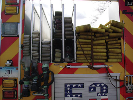 |
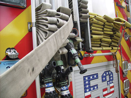
| (3) The hosebed setup. |
Know Your Response Area
The city of Meridan, Connecticut, has numerous structures that are set back from the road in excess of 300 feet. The city features many alley-like and one-way roads (photos 1, 2) that make apparatus positioning near the structures impossible or impractical, especially in times of severe weather such as heavy snowfall. Our city also has many nonstandpipe-equipped apartment complexes. These set-back structures, apartment complexes, and alley-like streets exceed the capacities of a traditional hoseline deployment. Therefore, the Meridan (CT) Fire Department (MFD) has employed the use of courtyard lays or leader lines.
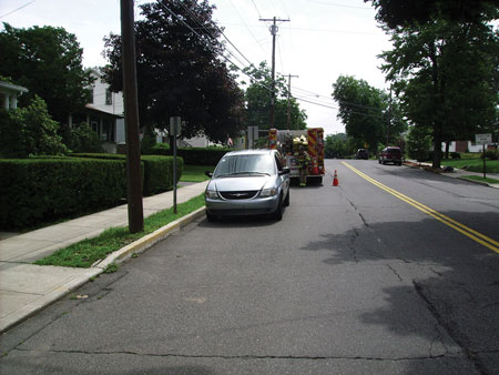 |
| (4) The apparatus is placed as close to the structure as safely allowable while ensuring there’s enough maneuverable space for the truck and subsequent responding engine companies. |
The Hosebed
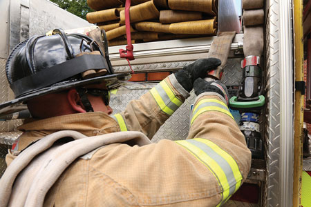
As previously mentioned, the MFD runs mostly three-firefighter engine companies. We have set up our engines to allow the best possible deployment of attack lines based on our staffing. We deploy three attack lines from the rear as preconnected minuteman loads. Photo 3 shows, from left to right, the following hoseloads: 200 feet of 1¾-inch, 250 feet of 1¾-inch, and 200 feet of 2½-inch hose. The 1¾-inch lines are equipped with a low-pressure/high-flow [50 pounds per square inch (psi)/175 gallons per minute (gpm)] breakaway nozzle; the 2½-inch is equipped with a smooth-bore 11⁄8-inch nozzle. Fifteen-foot jumpers are attached to all preconnected hoselines to facilitate disconnecting the preconnects from the apparatus without having to climb into the hosebed.
 |
| (5) The apparatus is placed as close to the structure as safely allowable while ensuring there’s enough maneuverable space for the truck and subsequent responding engine companies. |
Our 1¾-inch attack line deployment involves the nozzle firefighter shouldering the 1¾-inch preconnect minuteman load and laying toward the structure. The nozzle firefighter will ensure that the nozzle and the first coupling (i.e., the first 50 feet) are laid in a straight line with the final point of entry. The officer conducts size-up, directs the line, and then becomes the backup/control firefighter. The driver is responsible for ensuring that the hosebed has been cleared of all stretched hose, there are no kinks in the lines, the appropriate line is charged, the pump is set at proper pressure, and a positive water supply is secured.
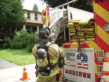 |
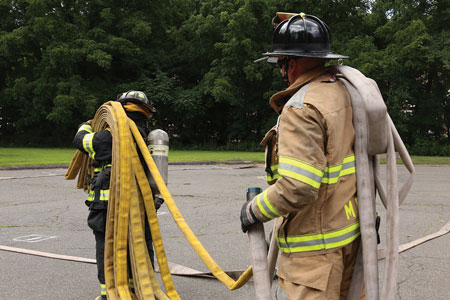
| (6) The officer shoulders the leader line and begins to lay the leader line to the structure. The driver chases kinks and assists with the leader line. |
As mentioned above, the city of Meridian has many structures that can be 300 feet or more from the nearest point where we can place apparatus, and it will be beyond the reach of our preconnect attack line. Since stretches of 1¾-inch hose may result in excessive friction loss and pump pressures, our department “fills out” the stretch with 2½-inch hose. Each department must decide on the maximum length of 1¾-inch hose that it can deploy without excessive friction loss and pump discharge pressures. This depends on (1) the flow characteristics of the department’s particular brand and grade of hose, (2) the intended gpm flow, and (3) nozzle pressure.
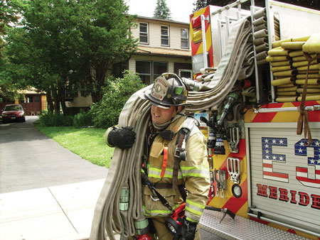 |
| (7) The officer shoulders the leader line and begins to lay the leader line to the structure. The driver chases kinks and assists with the leader line. |
Accordingly, the MFD has determined that the maximum practical length of a 1¾-inch hose stretch is 300 feet. We employ the leader line, which consists of laying 200 feet of 2½-inch hoseline equipped with a gated wye, attaching 200 feet of 1¾-inch preconnect from the gated wye, and laying in from that point. This effectively “places the pump” closer to the structure and reduces the need for long 1¾-inch hose stretches that can test the limits of the pump.
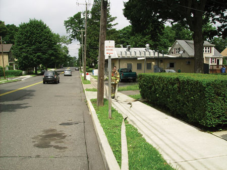 |
| (8) The leader line has been completely laid out. |
Authors’ note: The minuteman load is essentially an inverted flat load – a single-wide stack of hose loaded on top of the nozzle. One firefighter deploys it by placing the stack of hose on his shoulder with the nozzle on the bottom of the stack. This allows hose to flake off the top of the stack as the firefighter stretches toward the fire. The MFD does not pack the entire line as a minuteman load; we pack the minuteman so that we always have 150 feet resting on our shoulders. We then pack the remaining hose as a flat load.
 |
| (9) The officer begins his 360° size-up. |
Deploying the Leader Line
Deploying a leader line is not complicated but, as with all firefighting skill sets, it takes repeated training to ensure the stretch goes smoothly. The MFD has tried several methods, and we have found that the most effective way to deploy this hose configuration is to get the whole engine company involved. Each member has a specific assignment; when done correctly, this allows for a smooth process.
 |
| (10) The officer begins his 360° size-up. |
Everything starts with proper apparatus positioning. As always, we preplan our first-due area so we are aware of the best spot for apparatus placement. Ideally, we want to place the apparatus as close to the structure as is safely allowable, all the while ensuring we have left enough maneuverable space for the truck and subsequent responding engine companies (photos 4, 5). When possible, we position the rear of the apparatus toward the fire; this facilitates stretching in the direction of the fire and the apparatus being able to reverse-lay hose toward a hydrant. This may require an engine company to “back down” toward the fire.
 |
| (11) When deploying the leader line, you must pull it completely clear of the hosebed. Otherwise, it can obstruct the other hose loads and interfere when you are attempting to lay the five-inch hose to a hydrant. |
Next, the officer will grab the gated wye, shoulder the 200-foot 2½-inch preconnected minuteman load, and begin advancing (photos 6, 7). The officer will then advance the line completely, and the driver will clear the bed of remaining hose and chase kinks (photo 8). Next, the officer will begin his 360° size-up (photos 9, 10). In photo 11, when deploying the leader line, we pull it completely clear of the hosebed. Otherwise, it can obstruct the other hose loads and interfere with laying the five-inch hose to a hydrant.
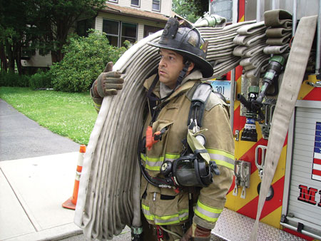 |
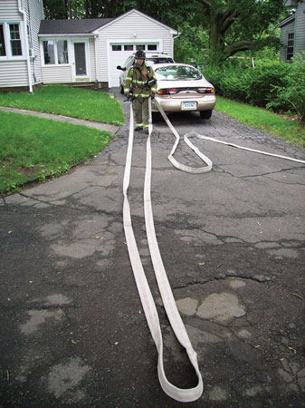
| (12) The nozzle firefighter shoulders the 150-foot 1¾-inch preconnected minuteman load and advances it forward enough so the driver/engineer can shoulder the remaining 100 feet of flat-loaded hose and disconnect the line from the jumper (pony) line. (Photo 12 by Michael Clark; photo 13 by Matt Van Ness.) |
The nozzle firefighter will then shoulder the 150-foot 1¾-inch preconnected minuteman load and advance it forward enough so the driver/engineer can shoulder the remaining 100 feet of flat-loaded hose and disconnect the line from the jumper (pony) line (photos 12, 13). Understand that this is a “modified” minuteman load, with the first 100 feet being flat loaded. This means the nozzle firefighter shoulders 150 feet of hose and the driver/engineer clears the remaining 100 feet from the hosebed. This happens with a normal deployment; but when using the leader line, the driver does not just clear the bed but actually shoulders the remaining 100 feet of hose and disconnects from the jumper.
 |
| (13) The nozzle firefighter shoulders the 150-foot 1¾-inch preconnected minuteman load and advances it forward enough so the driver/engineer can shoulder the remaining 100 feet of flat-loaded hose and disconnect the line from the jumper (pony) line. (Photo 12 by Michael Clark; photo 13 by Matt Van Ness.) |
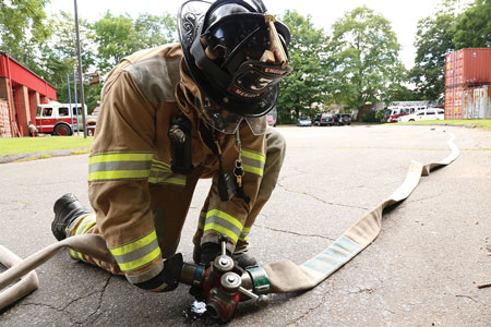
Once the 1¾-inch preconnect is disconnected from its jumper (pigtail/pony section), the nozzleman and driver/engineer will carry it to the wye at the end of the 2½-inch leader line (photo 14). The driver will then lay down his line, connect it to the gated wye, open the gate, and ensure the second gate is closed (photos 15, 16).
 |
| (14) After the 1¾-inch preconnect is disconnected from its jumper (pigtail/pony section), the nozzleman and driver/engineer will carry it to the wye at the end of the 2½-inch leader line. (Photo by Matt Van Ness.) |
Authors’ note: Using the gated wye now allows the other arriving engine companies to attach and stretch the backup or second attack line.
The nozzle firefighter will now begin to advance toward the structure, laying the line out as he goes (photos 17-19). He then lays the first 50 feet of hose and the nozzle in a straight line with the final point of entry, ensuring the nozzle and the first coupling are together (photo 20). This allows him to advance the first 50 feet. He then dons his self-contained breathing apparatus face piece at the door and makes entry (photo 21). The driver will make sure there are no kinks.
 |
| (15) The driver lays down his line, connects it to the gated wye, and opens the gate. (Photo by Matt Van Ness.) |
Saving at the Pump
Let’s look at what pump pressures you will need. Consider that, in all cases, water supply is adequate to meet your needs. When deploying a conventional attack line – 200 feet of 1¾-inch hose with a 100-psi combination nozzle – you want to flow 150 gpm to maintain a nozzle pressure of 100 psi (30 psi/100 feet of friction loss).
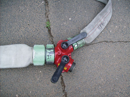 |
| (16) The driver then ensures that the second gate is closed. (Photo by Michael Clark.) |
Considering that friction loss varies greatly with the brand and grade of hose, the friction loss in 1¾-inch hose at 150 gpm averages to about 30 psi, according to various friction loss charts. The friction loss in 2½-inch hose flowing 150 gpm averages to approximately 3 psi. Again, averaging the various friction loss charts, connecting a second 1¾-inch hoseline that is flowing 150 gpm to the gated wye would raise the friction loss in 100 feet of 2½-inch hose flowing 300 gpm to approximately 12 psi. Remember, doubling the gpm basically quadruples the friction loss. We can calculate the pump discharge pressure of the leader line layout as follows: (Nozzle pressure) + (Friction loss in 1¾-inch hose) + (Friction loss in 2½-inch hose) = Pump discharge pressure (PDP). We can effectively flow 300 gpm through two 200-foot 1¾-inch handlines that are more than 300 feet away from the pump.
 |
| (17) The nozzle firefighter advances the line toward the structure, laying it out as he goes. (Photos 17-19 by Joe Scaglione.) |
Again, depending on your department’s target gpm flow, friction loss in your brand and grade of hose, and the intended nozzle pressure, long stretches of 1¾-inch hose may not be practical or efficient. This is how the leader line pays huge benefits. By deploying the larger diameter hoseline, friction loss is greatly reduced, and we effectively bring the pumper closer to our attack point. Also, for simplicity, we have kept the hoseline diameter, lengths, nozzles, and pressures equal. If any hoseline is different, then the hoseline with the highest friction loss would be used to determine the PDP.
 |
| (18) The nozzle firefighter advances the line toward the structure, laying it out as he goes. (Photos 17-19 by Joe Scaglione.) |
This article is not trying to dictate policy or procedures for your department or alter any of your strategies and tactics. The leader line is just another tool in the proverbial “toolbox,” and it is not without its inherent problems. Although the leader line allows us to extend the reach of our pump, the relief valve does not aid in relieving the pressure of a line when it is shut down. If you are flowing two 1¾-inch handlines at 150 gpm simultaneously and you suddenly shut down one line, it will raise the pressure of the line still operating. This could create a dangerous situation for the firefighters operating the handlines.
 |
| (19) The nozzle firefighter advances the line toward the structure, laying it out as he goes. (Photos 17-19 by Joe Scaglione.) |
As with any other skill set we are asked to perform, training is key to a successful operation. During training, the nozzle and backup firefighters must be in control of their lines and maintain proper body mechanics to absorb any of that additional pressure that may carry over from a line being shut down. Also, if a line is to be shut down, communication between the firefighters on the handlines and the pump operator is vital (as it is in all fireground operations). After notifying the pump operator that you are shutting down your handline, also notify the other hose team of your intentions and allow the pump operator to throttle down and allow the other hose team to prepare for the additional pressure surge.
 |
| (20) Here, the first 50 feet of the line is laid straight with the final point of entry. (Photo by Michael Clark.) |
Authors’ note: Special thanks to all of the MFD members and administration who, through their support and dedication to training, made this article possible. Special thanks to MFD photographer Matt Van Ness, who was instrumental in the media needed in preparation for this article.
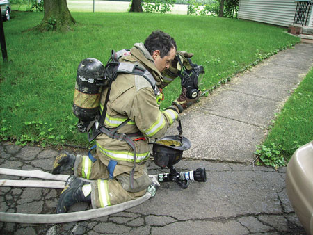 |
| (21) The nozzle firefighter secures the nozzle and the coupling as he dons his self-contained breathing apparatus face piece. (Photo by Michael Clark.) |
MICHAEL CLARK is a 20-year fire service veteran and a lieutenant with the Meriden (CT) Fire Department. Clark spent six years with the Durham (NC) Fire Department as a driver/engineer and assisted in recruit training. He was also a firefighter with the Rockville (MD) Volunteer Fire Department. He has an associate degree in public fire protection from Montgomery College and is a State of Connecticut and Pro Board-certified fire service instructor II and fire officer II. Clark is also an adjunct instructor with the Wolcott State Regional Fire School.
JOE SCAGLIONE is a 15-year fire service veteran and a lieutenant with the Meriden (CT) Fire Department. Scaglione has a bachelor’s of science degree in biochemistry from the University of Connecticut. He is a State of Connecticut and Pro Board-certified fire service instructor III and fire officer II as well as an adjunct instructor with Naugatuck Valley Community College Fire Technologies Program, the Connecticut State Fire Academy, and the Wolcott Regional State Fire School. He is an NFPA 472 hazardous materials technician and a former industrial firefighter with Hamilton Sundstrand Fire, Rescue, and Emergency Services. Scaglione is a certified rescue technician and a member of the Connecticut USAR Task Force Team and the New Haven Area Special Hazards Team. He serves on the IFSTA Essentials 7th edition committee and is a certified State of Connecticut fire marshal who serves as deputy fire marshal for the towns of Portland and Wolcott, Connecticut.
Improving Preconnect Function and Operation
Engine Company Operations: The “Ins” and “Outs” of Fire Department Connections
Engine Company Operations: Simplifying the Hose Stretch with Strategically Placed Loops
Appliances Increase Versatility of Large-Diameter Hose – Engine Company Operations
Fire Engineering Archives

