A PRACTICAL APPROACH TO LARGE-DIAMETER HOSE

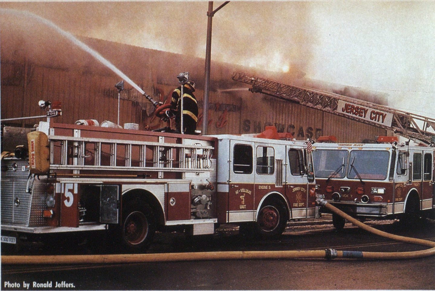
Photo by Ronald Jeffers.
Large-diameter hose (LDH) advocates say that LDH is the “do all and end all” of moving water to the fire scene. Some tout claims of phenomenal flows of water over great distances, and others would have you believe that you need nothing else— other than maybe a few preconnected handlines. My experience has been that LDH is the most effective way to move maximum quantities of water over distances that are practical for hoselays.
Following is a “nuts-and-bolts” approach to the equipment used and the normal application of LDH on the fire scene. Others have used this hose in creative ways. During Philadelphia’s One Meridian Plaza high-rise fire, for example, firefighters brought fiveinch LDH up 23 floors to replace an ineffective standpipe system. In other cases, LDH was used to bypass a broken water main to supply water to entire sections of a community. These and other extraordinaryprocedures are far removed from the normal uses of the hose. Basically, fourand fiveinch LDH was designed as a supply line between the hydrant and the pumper on a forward-lay or between the fire scene and the pumper in a reverse-lay situation, as well as to be an excellent method for supplying master stream devices, sprinklers, and standpipes.
So don’t sell your tanker and scrap your 2’/2-inch hose just yet. First let’s explore the practical applications of
I.DII
The basic equipment needed for 1.1)11 operations depends on the following factors:
- The methods of supplying the water into the LDH.
- The effective ways to distribute the water coming from the supply line.
- I he auxiliary equipment used in conjunction with LDH.
For the sake of uniformity, 1 will refer to five-inch LDH with Storz couplings throughout this article when describing appliances and adapters used with this hose.
SUPPLYING THE LINE
Some fire departments mistakenly believe that their pumpers must be modified with a special five-inch discharge before they can pump an LDH line. This is not true. Several other options are available.
A 1,250-gpm pumper is capable of discharging its entire capacity through a single 2‘/2-inch discharge. A 2‘/i-inch by five-inch adapter can be used to pump this water into the line. When purchasing this adapter, as well as LDH fittings, specify a 30-degree elbow type, as it relieves the hose and valve of much of the weight and provides a smooth connection without kinking. When making this connection, for safety’ reasons, choose a discharge on the right side of the pumper, away from the operator, and also one that is connected directly to the pump’s discharge manifold, which will give the best performance. Avoid using discharges in the front or rear of the apparatus; the long runs of pipe have many bends and will inhibit your ability to properly’ supply this line.
When specifying a new pumper, request a valve larger than the standard 2‘/2-inch for supplying the LDH discharge. The manufacturer undoubtedly will tell you that these larger discharges now must be placed away from the pump operator and controlled by a slow-acting valve to reduce water hammer, as per the recommendations contained in NFPA 1901 (1991).
Another method of supplying water to the LDH in a forward-lay situation is to use the five-inch hydrant connection. This could run in size from 2½ to five inches, depending on the hydrant’s threaded discharge. If possible, choose the larger “steamer” connection; it is the most efficient way to get the maximum water from the hydrant. I sing the 21/2-inch connection, however, will not severely inhibit tlie operation. These connections also should be at a 30-degree angle, to reduce strain.

(Photo by author.)


(Photos by Ronald Jeffers.)

(Photo by Ronald Jeffers.)
file third method of getting water into the line is to use a threeor fourinlet clappered Siamese. It can be connected to the five-inch line, and up to four conventional 2’j-inch lines can be used to feed the appliance. Although you might consider this device optional, in the past it has proven its worth and effectiveness when a pumper laying a five-inch line empties its bed and another unit with conventional 2½or three-inch hose assumes the task of completing the lay.
DISTRIBUTION
Size-up, which determines whether a forward or reverse lay is used, dictates the best method for distributing the w ater at the fire scene and also the appliances needed to accomplish the mission.
I he pumper inlet valve can be used at the end of a forward lay to connect the LDH to the pumper’s suction inlet. These shutoff valves are available in several styles and operating arrangements, and most have a pressure-relief device. This feature is extremely important and, if properly set, helps reduce the damaging effects of water hammer as well as prevents overpressurization of the supply line during sudden shutdowns. The recommended adjusting procedure is to set the valve 10 psi over the highest hydrant pressure reading or standard relay-pump pressure. The lower the dump pressure setting, the quicker the valve response to sudden pressure surges.
Most of these valves have the 30degree angle incorporated in their design, and some have air bleeders that are used to expel air when the line is first charged. Do not use a straight sixby five-inch adapter in the the pumper’s suction inlet without a relief valve.
The distribution manifold also comes in several configurations and with different options and features. The most versatile has a five-inch inlet, four gated 2’/2-inch outlets, a five-inch gated discharge, and a pressure gauge. An appliance configured in this manner allows the option of supplying any combination of pumpers and master stream devices, provided that the incoming water supply is adequate.


(Photos by author.)
Attack lines can be operated from the manifold; in doing so, however, the element of pressure control is lost when lines are of unequal length or volume. Unlike a pumper’s adjustable relief valve, the manifold cannot be expected to react to increases in pressure due to the operation of the nozzles. The relief valve on the manifold must be preset at the highest pressure anticipated to supply standpipes, monitors, ladder pipes, and so on. The maximum available setting usually is 200 psi, which might be considerably higher than is safe for short stretches of attack lines. If at all possible, the best course of action is to supply a pumper with the LDH and control discharge pressures with the pumper.
The fiveby 21/2-inch adapter can be used to supply sprinklers and standpipes as well as master stream devices such as a portable monitor. The “sexless” nature of the Storz connections allows these fittings to be used on either end of the hose, and the same adapter used to supply the LDH can be transformed into a discharge simply by using a double male threaded adapter.
AUXILIARY EQUIPMENT
The following equipment may be useful, depending on the operation.
LDH spanner tvrenches obviously will be needed to assist in connecting and disconnecting the quarter-turn couplings. Be sure to have an ample number of these inexpensive wrenches on hand —they come in handy on long hoselays, especially when quick winter breakdowns are necessary to prevent freezing.
A hose wringer looks like a double rolling pin and is used to drain the water out of the LDH. In most cases, walking a six-foot pike pole handle between two personnel at waist level quickly does the same job.
Hose bridges specifically for LDH operations are available, but they are heavy, cumbersome, and take up a considerable amount of space on the apparatus. They could prove valuable during a long operation where traffic must cross the line, but it might be wise to store these bridges at quarters and special-call them when necessary.

(Photo by author.)
While on the subject of crossing the LDH, there is a very good possibility that cars and small trucks with low ground clearance will puncture the LDH, especially five-inch. To try to avoid this problem, cars that must cross the charged hoseline should be directed to proceed over it slowly without stopping. If the vehicle stops as the wheel comes in contact with the hose, it tends to push the hose and cause abrasive damage.
Fire apparatus can cross the line without causing damage, but the result will be a water-hammer effect, much like that caused by rapidly opening and closing a valve. A good rule of thumb, whenever possible, is to avoid crossing charged lines and never run over or strike couplings.
The four-way hydrant valve allows the LDH to be charged at hydrant pressure, and when a pumper is available it can hook up to the valve and feed the LDH at pump pressure without interrupting the flow to the scene. In most cases, if you have adequate hydrant pressure and reasonable expectations of the supply line, this expensive valve rarely is needed.
Two short hose lengths of 25 and 50 feet will prove very valuable in completing hoselays, especially when the coupling stops at the rear tailboard, as it usually does. They also can be used to connect the manifold’s five-inch discharge to a nearby pumper without pulling a full 100-foot length.
OPERATING PRESSURES/EXPECTATIONS
You must consider several factors when attempting to determine the available flows and capabilities of LDI1 supply line. First, the normal safe operating pressure of LDH is up to 200 psi. Assuming that a pumper has an adequate water supply to feed the line, subtracting from the 200 psi available residual or nozzle pressure needed on the receiving end determines the portion of the pressure that can be used to overcome the friction loss in the hoselay.
When relaying to another pumper whose operator wants a 20-psi incoming residual pressure, for example. 180 psi would be available to overcome the friction loss between the pumpers. In another example, if the connection were directly to a portable monitor requiring an 80-psi nozzle pressure. 120 psi would be available to overcome the friction loss between the pumper and the appliance.
The friction loss in the LDH supply line, as with all hose, is determined by the gpm flow; therefore, the higher the expected flow, the shorter the line must be. The friction loss figures quoted in the manufacturers’ literature are based on actual performance and are somewhat lower than the theoretical calculations using published hydraulic formulas. The basic, single line friction loss formula is FL = C X Q X L, where FL = friction loss per 100 feet; C = coefficient from chart; Q = gpm flow divided by 100, squared; and L = hose lengths of 100 feet.
The coefficients quoted in the NPFA Fire Protection Handbook and the IFSTA fire streams charts are 0.08 for five-inch and 0.2 for four-inch line.
Using this formula, 1,000 gpm flowing in 100 feet of five-inch supply line will develop eight psi of friction loss, while the same quantity in four-inch line will require 20 psi per hundred.
In the first example of a pumper at a hydrant, were a second attack pumper to be supplied at the fire scene, it easily could be calculated, using the above figures, that 1,000 gpm could be relayed 2,250 feet (180 psi available divided by 8 = 22.5 100-foot lengths). In the same example, if you were relaying with four-inch line, the limit would be 900 feet.
The difference in water-carrying capabilities between fourand fiveinch LDH becomes even more apparent in the second example. If the monitor were being fed by five-inch line and were flowing 1,000 gpm, it could be supplied 1,500 feet from the pumper (120 psi divided by 8 = 15 100-foot lengths). Applying the same conditions using four-inch hose, the limit would be only 600 feet.
As these examples show, five-inch LDH is far more effective than fourinch LDH, which has 2’A times more friction loss at any given flow. This important difference should be considered, especially if the SOPs call for a forward lay from hydrant to fire using only hydrant pressure.
The handling characteristics of fourand five-inch LDH are very similar. There are two factors that might make four-inch more desirable than five-inch LDH. The first factor is the hosebed configuration and cubic feet of space available for storage. The cubic feet of hosebed space needed per length is approximately 3-2 for five-inch LDH, as opposed to 2.3 cubic feet for four-inch.
The second factor is cost. Five-inch LDH is estimated to cost about 20 percent (approximately SI per foot) more than the four-inch. If funding is critical, instead of sacrificing the performance characteristics of five-inch LDH, fewer lengths could be purchased during the initial acquisition and others could be added later.
If the concern is to be compatible with a neighboring company or mutual-aid department presently using four-inch supply line, a fourby fiveinch Storz adapter could be used to complete the connection.
When considering making a commitment to large-diameter supply line, the efficiency and effectiveness of the five-inch line far exceed those of four-inch line.
HANDLING THE HOSE
When working with the LDH, a few important considerations can help avoid problems during the operation. While laying the line out, for example, the apparatus should move at eight to 10 miles per hour. At this speed, the couplings will clear the tailboard and the hose will flow smoothly to the ground. If at all possible, lay the hose to one side of the street, preferably the hydrant side, to help avoid having apparatus and traffic cross it once it is charged.
Picking up the large and bulk}’ hose can be accomplished effectively if you allow the apparatus to do some of the work. After the lengths have been disconnected and drained, the apparatus can be backed up or driven forward over the hose while it is being passed up to the personnel in the hosebed. The apparatus should move at a comfortable pace, and one person should be communicating instructions to the driver. This method makes dragging or carrying the hose to the rear of the apparatus unnecessary. Remember that the LDH must be loaded so that the couplings pull straight off the bed without flipping.
When comparing the pick-up time of hose in a water-supply situation, consider a routine 400-foot lay. If using conventional jacketed 2¼or three-inch line, a parallel stretch of eight 50-foot lengths on each line, or a total of 16 lengths, would be needed, and all would have to be disconnected, drained, rolled, and dried and the replacement hose reloaded. If LDH supply line is used, only four 100-foot lengths would have to be drained and reloaded, since cleaning (other than brushing off heavy dirt it may have collected, if necessary) and drying are not required.
Some of the other LDH features that add to its desirability involve safety. If a length becomes punctured, for example, it will spurt water like a fountain but will not burst. We have continued operating for long periods of time with a salvage cover over a leak without interrupting the operation. This feature also helps to allay fears of using a single supply line and losing the entire operation to a burst length.
Because of the very low friction loss characteristics of LDH, the hose operates at pressures lower than those for conventional fire hose. The lower pressure increases the gallonsper-minute capacity from the pumper (remember the rating plate —maximum capacity at 150 psi pressure). With the pumper operating at lower pressures, there is less wear and tear on the engine and also a fuel savings, which could become critical during a long-duration operation.
LDH supply line is the safest and most effective method—other than having a hydrant in front of ever}’ structure in the district—for delivering maximum fire flows from the water source to the fire scene over distances that are practical for hoselays.

