Emergency Personnel’s Guide to MICROCOMPUTERS
features
COMPUTERS
Microcomputers have been receiving a great deal of media attention. It’s difficult to read a newspaper or magazine without seeing some mention of the impact of computers. One television network even offers a weekly prime-time program on microcomputer news and information. Chances are if you look in your local bookstore, you’ll see a shelf labeled “Computers and Data Processing,” offering everything from how-to books to choosing a game computer to programming in Cobol.
Despite the quantity of information available, little has been written to help fire service and emergency medical service (EMS) managers choose an appropriate microcomputer system and use it on the job.
This is the first of a four part series of articles designed to give fire service and EMS managers a working knowledge of microcomputer technology. The series begins this month with an introduction to microcomputer hardware. Future articles will explore fire and EMS software and determining your data processing needs. The series will conclude with specific advice for selecting a microcomputer system that’s right for you.
HARDWARE: TOOLING UP FOR SUCCESS
Both fire departments and EMS agencies have recognized the value of tools. A fireground officer, for example, uses a portable radio to send and receive critical information. The officer has the ability to communicate verbally, but using the radio as a communications tool, he can extend his communication range and thereby increase coordination and efficiency. Similarly, a paramedic uses an electrocardiogram (EKG) as a tool to diagnose heart action abnormalities. While the paramedic may suspect a particular arrhythmia from the patient’s appearance and vital signs, an accurate diagnosis can only be confirmed with an EKG.
Tools, properly used, can increase efficiency and productivity. Tools can even help provide information for accurate decision making. Firefighters, emergency medical technicians (EMTs), and paramedics responding to emergency calls are trained in the use of hundreds of tools. The effectiveness of their actions are directly dependent on their ability to use those tools effectively and reliably.
If line personnel are provided with sophisticated tools, it would follow that fire service and EMS managers would have even more sophisticated tools. A tour of a typical manager’s office should offer some insights.
Immediately upon opening the office door, the largest and most obvious management tool appears in a corner of the room. It’s the file cabinet.
Approaching the manager’s desk other tools appear. First, the telephone, an electronic device invented in the 19th century. Other tools include a stapler, a dictionary, and a small dish containing paper clips. One 20th century management tool in the center of the desk is a $12.95 pocket calculator.
In an adjoining room sits the most complicated and sophisticated tool in this manager’s office. It has 52 keys and is electrically powered for the convenience of its operator. The tool, an electric typewriter, is so sophisticated that the manager has hired an assistant, called a secretary, to operate it. It’s obvious that the modern technology that can make fire service and EMS managers more effective has yet to enter this office.
Micro power
Three or four years ago computer technology was expensive and difficult to use. Managers were required to give control of valuable fire/EMS records and data to “systems analysts,” “programmers,” “technicians,” and other “computer experts.” Computer technology was associated with high cost and the aggravation of having to rely on people who knew little about fire service or EMS management.
Today, the evolution of the microcomputer has created a new era for fire and EMS officials. The microcomputer has evolved into a powerful, multipurpose management tool that is inexpensive, easy to use, and allows managers to exercise both control and creativity. Consider just a few examples:
- Immediate access to operational information such as response time by census tract, types of runs by response zone, volume of calls by time of day and day of the week, total service time by a unit, etc. Personnel rosters can be immediately called up alphabetically, by seniority, or by shift. Overtime assignment lists based on rank, shift, qualifications, and rotation equality can also be keyed.
- The ability to share experiences and ideas with other fire service and EMS professionals on a national computer information network.
- Immediate updates to sprinkler and standpipe lists, edits of rules and regulations, response protocols, disaster plans and street lists. The power to generate 15 code violation letters in one hour.
- The ability to revise and print a line item budget in 10 minutes, generate weekly payrolls, perform hydrant flow calculations.
- The ability to provide interactive training and testing of personnel any hour of the day or night.
All of these tasks and hundreds more can be performed by fire service and EMS managers using a microcomputer system priced at less than $5,000.
UNDERSTANDING HARDWARE
The term “hardware” refers to the tangible electronic components that compose a microcomputer system. The keyboard, computer circuitry, and video monitor are all examples of hardware.
continued on page 32

continued from page 30
In contrast, “software” refers to specific sets of programmed instructions designed to enable the hardware to perform specific tasks. Software may be written to enable a microcomputer to track response information, manage ambulance billings, or print the weekly payroll.
It’s important to understand that both hardware and software are required for the microcomputer to function. The term “microcomputer system” is used to describe electronic hardware and compatible software that have been developed to perform specified tasks.
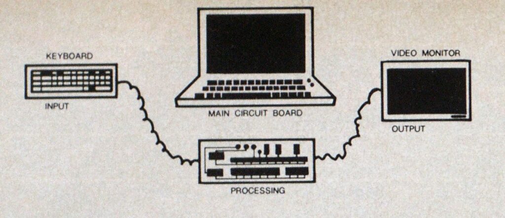
If a microcomputer system is viewed from the outside, the most visible pieces of hardware are the keyboard, the box containing the majority of the microcomputer’s electronic circuitry and the video screen, called a CRT (cathode ray tube) or monitor.
In figure 1, these components have been separated into three basic functions: data input, data processing, and data output. In this simple illustration, data is entered into the computer by use of the keyboard. The data is then manipulated by the microcomputer’s electronic components and programming. Finally, the data is output and displayed on the microcomputer’s monitor. In referring to the computer’s data handling capabilities, data input and output are assumed and the term “data processing” has been left to identify the microcomputer’s main function.
A GUIDED TOUR
In order to gain a more in-depth understanding of the microcomputer, let’s follow the flow of data through the three steps of our simple microcomputer diagram.
Data entry
The data entry point in our diagram is the keyboard. Keyboards generally have at least 50 keys positioned in rows like those found on a typewriter keyboard. Each key is an electrical switch that signals that a letter, number, or punctuation mark has been selected. The keyboard is, however, more than an electronic switch box.
When a character is depressed, a device called a “keyboard encoder” identifies the proper character converting it to a simple “binary” code. Binary defines a condition where there are but two possible alternatives. The conditions used in the computer world are “ON” and “OFF” indicated by the binary code “1” (for ON) and “0” (for off). It’s important to understand binary because literally everything that happens within a microcomputer is based on this “ON/OFF” (“1/0”) condition.

Most microcomputers manufactured today use a standard coding system called ASCII (American Standard Code for Information Interchange). It consists of a series (or “string”) of “l”s and “0”s that represent 96 uppercase and lowercase letters, numbers, and symbols (punctuation, asterisk, etc.), plus 32 computer control characters, a total of 128 possible characters.
ASCII’s limit of 128 characters can be explained by examining the length of a binary string. If a binary code is one “bit” long (one number long), there are only two possible conditions, “1” or “0.” If a binary code is two bits long, there are four possible combinations; “00,” “01,” “10,” “11.” As you can see from figure 2, the number of possibilities rises exponentially as the length of the string increases.
ASCII code uses a string of seven bits to represent characters, hence the total of 128 possible characters represented by a string of seven bits. An additional eighth bit is used to test the accuracy of the string by indicating whether the sum of the first seven digits should be odd or even. This eighth bit, called a “parity bit,” performs a quality control test that is particularly valuable when ASCII characters are being transmitted from one microcomputer component to another.
A string of eight bits is used to represent a character called a “byte.” In practical terms, the letter “A” or “B” or the number “5” or a blank space separating two words each requires one byte or eight bits of ASCII code.
Now that characters have been entered and encoded by keyboard circuitry, let’s follow their path into the heart of the microcomputer.
Processing
If the top is lifted off a microcomputer, a large printed circuit (PC) board is obvious. The PC board is a glass epoxy laminate containing holes for mounting electronic components and printed wiring that electrically interconnects the components as required.
The most common components mounted on the circuit board are called integrated circuits (ICs) or simply “chips.” The “chips” are the result of decades of research and advances made in the electronic semiconductor industry. Semiconductor technology has evolved from tubes to diodes to transistors. Miniaturization has allowed for the electronic equivalent of as many as 500,000 transistors to be placed inside a chip smaller than a postage stamp.
THE CPU
Of all the chips mounted on the microcomputer’s main circuit board, the most complex is the central processing unit (CPU). The CPU is the microcomputer’s brain. It is the component primarily responsible for interpreting instructions and executing programmed functions such as mathematical computations and data processing. More than 100 processing steps have been pre-programmed in the CPU and are ready to be activated by simple commands.
Circuits inside the CPU are equivalent to thousands of microscopic switches that are set either “ON” or “OFF” by the binary instructions the CPU receives. It’s these switch settings that select, sort, compute, or otherwise process data entering the CPU.
In order to synchronize the operation of the CPU’s switches, a quartz crystal or “clock” is used to control the timing of data bits entering the CPU. A common clock frequency of 4 MHz (megahertz) limits data flow to the CPU to 4-million times per second. While this rate is essential for organizing the flow of data to and from the CPU, it is not likely to handicap even the fastest touch typist.
continued on page 34
continued from page 32
Eight bits vs. 16 bits
In general, a microcomputer operating at 4 MHz takes longer to process information than a microcomputer with a processor operating at 8 MHz. But it’s not always that simple. CPUs themselves have different capabilities.
Remember the explanation of bits? Well, CPUs are available in “8 bit” and “16 bit” varieties. An 8-bit CPU can process eight bits of instruction code (or programming) simultaneously. A 16-bit CPU, on the other hand, can process instruction codes 16 bits at a time.
On the surface, it may seem that the 16-bit processor is twice as powerful as the 8-bit processor, but that’s an understatement. Remember our binary chart. Eight bits allows 256 possible conditions. Sixteen bits, on the other hand, allows for 65,536 possible conditions. That makes 16-bit processors very powerful indeed.
The Apple IIE, the Kaypro 2 and the TRS-80 Model IV all use an eight-bit CPU. The IBM PC uses a CPU that can process 16-bit “words” internally, APPLE’S new Macintosh computer has a CPU capable of processing 32-bit words internally.
While it’s easy to get excited by all this technology, a word of caution is necessary. Because of the limitations of software and other computer components, there’s not as much difference between eight-bit and 16-bit microcomputers as you may expect. In general, 16-bit micros run faster and are capable of utilizing more powerful software packages. Eight-bit micros will still be around for a long time.

FIGURE 3
RAM (Random Access Memory)
Aside from the CPU, other components are required to make the microcomputer function. Random Access Memory (RAM) refers to chips whose main function is to store data. You have probably heard of computers having 64K RAM. The K refers to roughly 1,000 bytes (1,024 actually) of data. A 64K microcomputer can hold over 64,000 characters of data electronically.
Like the CPU, RAMs contain thousands of switches that are set by input data and electrically held in position until changed by additional data. RAMs are a “volatile” data storage medium. Volatile refers to the fact that memory storage is dependent on an uninterrupted supply of electrical power. If you have heard stories of people losing pages of material from their word processor because of a power failure, it’s likely that the user was storing text data in RAM.
While RAMs can store written text, they are most frequently used to store the CPU instruction codes called “computer programs” or “software.” If someone wishes to use a microcomputer as a word processor, for example, the word processing software is loaded into the computer’s RAM where the CPU can instantly “address” or locate thousands of sets of instructions as required to perform the word processing function.
ROM (Read Only Memory)
Another essential element of a microcomputer is the components called ROM or Read Only Memory. A ROM stores information like a RAM except that a ROM’s memory pattern is not volatile but permanent. The thousands of “ON” and “OFF” switches were “burned” into position and do not reset when power is interrupted.
ROMs are used to store data that is required by the computer as soon as power is applied. The Apple IIC microcomputer, for example, uses an “auto-start ROM” to instruct the computer to delay one second then activate its software storage device called a “disk drive.”
Programmed instructions are “read” from the magnetically coded disks in the drive each time the computer’s power is switched on. This feature can be a time saver since it allows for the automatic loading of software when the main power switch is activated.
ROMs also perform other necessary functions. Those who have seen computer programs know that most program “languages” contain letters, numbers, and symbols and not the series of “l”s and “0”s that are understood by the computer’s CPU. The computer program languages were written to bridge the gap between the human brain, which thinks in terms of concepts and abstractions, and the microcomputer’s CPU, which understands only binary instruction codes.
In order to provide an electronic connection between the “higher level” programming language and the “lower level machine language” understood by the CPU, a pre-programmed ROM is used as a “translator.” The BASIC language instruction:
70 INPUT X: IF X < 30
THEN GO TO 160
is frequently converted to binary code by a translator stored in ROM.
OUTPUT
Once data has been entered through the keyboard and processed by the CPU, it must be output to the video monitor or another output device. In many computers, a “video generator” will address or locate that part of the RAM’s memory the CPU has used to store “display” data. The data stored at that address is then converted to signals that will be displayed on a video monitor. The video generator may be directed to different memory addresses for graphic displays such as bar charts and line graphs.
In a similar manner, data can be addressed and output to printers, plotters, telephone connection devices called “modems” or to the microcomputer’s disk drives. As you can see from figure 3, the disk drives have a central data storage function. The drives can be used to input software, to expand RAM memory by providing temporary data storage and to serve as output devices for data that has been processed. The software stored on disks in the disk drives is crucial to each phase of microcomputer operation.
Understanding microcomputer hardware is important, but it only gives you half of the picture. Next month, we’ll move from hardware to focus on the critical area of microcomputer software. We’ll look at the main categorries of software and discuss the application of specific types of software in fire service and EMS agencies.
A free computer information service is being offered by ON-LINE RESOURCES. Those interested in “checking in” can connect their microcomputers to a modem and dial 717-642-8380. For information on subscribing to the ON-LINE RESOURCES newsletter, write to: ON-LINE RESOURCES, P.O. Box 140, Emmitsburg, MD 21727.