Tandem Pumping
FEATURES

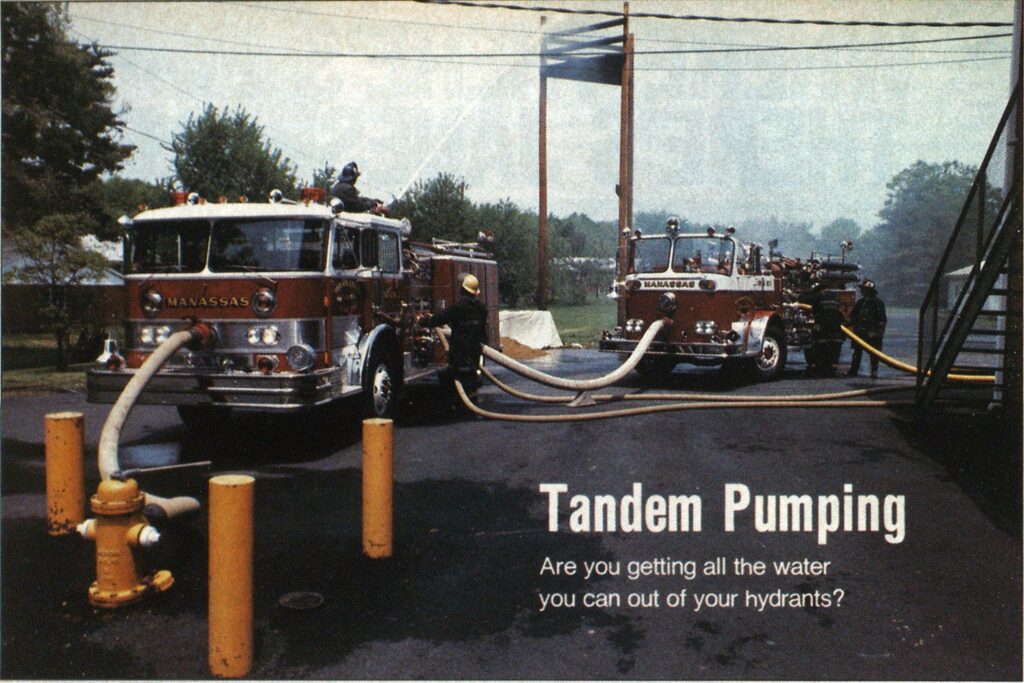
photo by James Lesnick
Are you getting all the water you can out of your hydrants?
Establishment of an effective water supply is vital to practically all successful fire suppression operations. Large fires frequently tax available fire department resources, requiring long hose layouts and many pumpers. A method of more efficiently utilizing department resources and available water in a water main is tandem pumping, i.e., two pumpers receiving their water supply from the same hydrant. Too often restricted as a hydraulics class curiosity, this operation can, with pre-planning and training, become an important and routine fire control mechanism.
Hydrants closest to an incident quickly become committed in the early stages of a fire. As the scale of the incident increases, so do the water requirements. Units responding on additional alarms must lay from more distant hydrants. This increases the amount of hose and pumpers necessary to relay the water, as well as the engine discharge pressures required to transmit the water, thereby reducing the amount of water capable of being moved. Frequently, a hydrant has a capacity that exceeds the limits of the pumper working from it. Tandem pumping allows an additional pumper to utilize this available water, thus eliminating the need for a longer lay from another hydrant and gaining the maximum advantage from the hydrant.
To be successful, tandem pumping requires preparation and pre-planning and several factors must be determined before attempting the operation on the fireground.
- First, hydrants should be identified as having sufficient flow for tandem pumping. As a rule of thumb they should, for maximum advantage, have an available fire flow of at least one and a half times the combined rated capacity of two pumpers, with a minimum of 20 psi residual pressure. For example, two 1,000 gpm pumpers require a hydrant with a flow of at least 3,000 gpm. Suitable hydrants should be indicated on maps, pre-plans, and in standard operating procedures (SOPs).
- Second, pumpers expected to participate must have the necessary equipment to establish a water supply. This may require the addition of adaptors, gated intake valves, proper sized hose lines, and possibly the alteration of existing pump piping. These requirements can have special significance if companies from other jurisdictions are expected to perform the operation with local units.
- Third, pump operators must be thoroughly versed and drilled in the theory and procedure involved in tandem pumping to allow for speed on the fireground.
- Fourth, fireground officers, pump operators, and water supply officers should be familar with suitable hydrants and apparatus and with SOP.
There are three methods of establishing dual usage of a hydrant that are readily suitable for most departments. Method one requires the second pumper to be able to hook up to a hydrant’s unused outlet (frequently 2V2 inches) after the first arriving pumper has utilized the primary outlet (frequently 4 1/2 inches). The hydrant must be shut down to effect this connection, unless individual gates are provided on the hydrant or applied by the pump operator before charging it. Available flow to the second pumper is limited by the size and length of the supply lines and by the pressure and size of the hydrant’s orifice (method 1).
photos by James lesnlck

Method 2A
- Position pumper A for soft sleeve hookup to hydrant.
- Hook up soft sleeve and charge the hydrant.
- Establish pumper A water discharge requirements.
- Position pumper B for hard or soft sleeve hookup to pumper A at the gated steamer intake.
- Attach any required ftttings to the gated intake.
- Hook pumper B’s soft or hard sleeve to gate valve.
- Slowly open the gate and charge the sleeve.
- Establish pumper B water discharge requirements and adjust pumper A discharge pressure to compensate for decrease in intake pressure.

Method 3
- Position pumper A for soft sleeve hookup to hydrant.
- Hook up the soft sleeve and charge the hydrant.
- Establish pumper A discharge requirements.
- Position pumper B for soft sleeve hookup to pumper A at the pump panel with an available 2 1/2-inch discharge outlet.
- Attach any required fittings to the soft sleeve and the outlet.
- Hook the soft sleeve to the outlet.
- Open discharge slowly and charge the soft sleeve.
- Adjust pumper A discharge pressure to compensate for the additional flow and maintain previous discharge pressure requirements.
- Establish pumper B water discharge requirements.
Method 1
- Position pumper A for soft sleeve hookup to the hydrant.
- Remove the 4 1/2-inch and both 2 1/2-inch hydrant caps.
- Connect pumper A to the hydrant.
- Attach 2 1/2-inch gated valves to the 2 1/2-inch hydrant outlets.
- Open hydrant and charge pumper A.
- Position pumper B as close as possible to the hydrant.
- Lay two supply lines to both gate valves and connect.
- Connect supply lines to pumper B intakes.
- Open gate valves and charge supply lines.
- Open pumper B intakes to receive water.
- Pumper A adjusts throttle and discharge pressure to compensate for any intake pressure loss.

Method 2B
- Position pumper A for soft sleeve hookup to hydrant.
- Hook up soft sleeve and charge the hydrant.
- Establish pumper A water discharge requirements.
- Position pumper B for hard or soft sleeve hookup to pumper A intake opposite the one hooked to the hydrant.
- Attach any required fittings to pumper B sleeve.
- Reduce intake water to pumper A by closing the hydrant or gated intake slowly. At the same time it will be necessary to increase the throttle to maintain the required discharge pressure.
- When the intake pressure on pumper A reads 3 psi or less, quickly remove the blind cap on the intake.
- Quickly hook pumper B sleeve to the open intake on pumper A.
- Re-establish full flow from the hydrant to pumper A while making throttle adjustments to maintain pumper A required discharge pressure.
- Establish pumper B water discharge requirements and adjust pumper A discharge pressure to compensate for decrease in intake pressure.

Method two involves hooking a supply line, preferably a hard or soft sleeve, from the second pumper to an unused steamer connection of the first pumper. Water that enters the first pumper in excess of the discharge requirements flows into the second pumper without affecting the discharge. This evolution can easily be established if done prior to charging the hydrant. If the first pumper is already pumping (which will usually be the case), the connection can still be made if the first pumper is equipped with a gated intake valve on the steamer connection to be used by the second pumper. After the sleeve of the second pumper is connected to the intake, the gate is opened, allowing water to flow to the second pumper. The first operator adjusts his throttle to compensate for the loss of intake pressure on his discharge requirements (method 2A).
If a gated intake is not provided on the primary pumper, the operation can still be effected, but it requires teamwork, timing, and skill. Intake water to the first pumper is slowly restricted by closing either the hydrant or intake valve to the point where all water entering the pump is being discharged. The pump is very close to cavitating at this point, therefore, the procedure must be done quickly to prevent pump damage and to limit discharge disruptions. The steamer connection’s blind cap (opposite the one hooked to the hydrant) is then removed—very little water should be expelled. The hookup is then made with the sleeve from the second pumper. Normal hydrant flow is now restored and excess water is available to flow into the second pumper (method 2B). Pump operators must be familiar with the internal piping of the apparatus, as water must flow through the impeller first before reaching the steamer connection to be used by the second pumper. Hence, not all intakes will be suitable.
Method two allows for the fullest utilization of the hydrant, but requires the greatest degree of preparation. Special fittings, most frequently a 4‘A inch male to a 5or 6-inch female, may be required to allow soft sleeves to be connected to steamer connections. Hard sleeve connections will require more manpower, more precise apparatus positioning, large diameter double females, and possibly a reducer. It is strongly recommended that if tandem pumping is to be a standard procedure, gated 4Vrinch male steamer connection valves be provided for soft sleeve hookup. This allows for the easiest and most rapid connection (method 2B).
Method three is easily accomplished and can be established under many varying conditions. The soft sleeve of the second pumper is connected to an available 2*4-inch discharge on the first pumper (method 3). This generally requires the use of several fittings, which may place stress on the internal pump piping and on the fittings themselves, especially if drain or discharge handle configurations prohibit direct hookup of a bell reducer. This evolution differs from relay pumping in that no specific quantity of water is transmitted to the second pumper. Water available to the second pumper is limited by the size and length of its supply line, by whatever the first pumper has established as its discharge pressure, and by the physical size restriction of the 2 Vi-inch outlet. This method, although easily accomplished, provides the least benefit to the second pumper and commits a discharge outlet on the first pumper that will restrict its available discharge potential to the fireground.
Several factors must be considered by the water supply officer before committing operations to tandem pumping:
- First, failure of the hydrant for whatever reason will mean the loss of a significant fire flow. For this reason, the argument is valid that the second supply line laid on the fireground should preferably be laid from a separate water source.
- Second, the mechanical breakdown of the first pumper, or the bursting of a supply line may, depending on the type of tandem pumping, shut down both pumpers.
- Third, pump operators must always be cognizant of their pump operations and estimate the impact on both pumpers before altering flow requirements. It should be remembered that in methods two and three, the first pumper will seek to satisfy its own discharge requirements before allowing water to flow to the second pumper.
- Fourth, additional pumpers removing water from different hydrants on the same main may render a once adequate hydrant insufficient for tandem pumping.
- Fifth, positioning two units for tandem pumping may block street access to the fireground and interfere with the deployment of additional companies, especially in methods two and three where positioning is restricted by the relative short length of sleeve connections.
Pump operators must train with these procedures until they fully understand their responsibility and can accomplish the evolution correctly and quickly, certainly in less time than it would take to lay to a further hydrant. Only when all the advantages and limitations are understood by everyone involved will this evolution become a practical and viable asset. Pre-planning and training is the key to allow tandem pumping to become a routine solution to complex water supply problems.

