By PAUL SHAPIRO
Fireground hydraulics has been and still is the method taught to pump operators for developing pump discharge pressure (PDP). It involves mathematical formulas as well as multiple concepts to measure water flow (gallons per minute), friction loss, exit or nozzle pressure (it’s called both), weight of water measured in pressure gain or loss, and so on. Everything taught in these classes is accurate as far as physics is concerned. However, some issues, such as friction loss in fire hose, can affect the accuracy of fireground hydraulics. There are many brands of fire hose, which vary in quality, and quality affects friction loss in hose. Let’s put the accuracy aside.
The formulas used for fireground hydraulics can be complicated, and some pump operators may find it difficult to do mathematical equations quickly under the stress of an emergency. To avoid having to calculate mathematical equations on the fireground, we have pump charts that display the PDPs. However, the correct PDP depends on the hose used. It is preferable to develop the correct PDP through flow tests based on the exact evolution being pumped—everything from the preconnected handline and booster line to the more complex operations such as relay pumping, extending lines, multistory buildings, and master streams—and placing these pressures on easy-to-use charts.
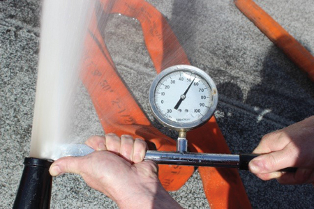
(1) A handheld pitot gauge. (Photos by author.)
Understanding Friction Loss
Delivering water on the fireground necessitates an understanding of some basic physics terms:
Friction loss: the water that rubs up against the wall of a vessel and causes turbulence that results in pressure loss. Water flow is measured in gallons per minute (gpm) as it goes through a nozzle.
Head pressure: the gain or loss of water caused by elevation. The gain or loss is roughly ½ pound per square inch (psi) per foot. When water rises, there is a loss. When it lowers, there is a gain.
Gauges: It’s important to properly read a gauge, which may necessitate the use of reading glasses or adjusting your location. Gauges are normally designed to be read in 10-psi increments.
Static pressure: the pressure reading of water in a vessel when it is not flowing.
Residual pressure: the pressure reading of water in a vessel after water is flowing. It’s the pressure left over.
Nozzle pressure: the pressure of the fire stream when it leaves the nozzle. It is also referred to as “nozzle exit pressure.”
Nozzle base pressure: the pressure at the nozzle’s inlet as measured by an inline gauge. This should be done on combination nozzles only.
This article discusses developing the PDP based on actual hose evolutions using flowmeters for flow tests, inline pressure gauges, and handheld pitot gauges. Although accuracy is the goal, we will not always be 100-percent accurate using these methods for a variety of reasons.
Friction Loss for Sections of Hose
Many hose evolutions are assembled on the fireground because the preconnected attack lines will not reach the target because of the engine’s location and other reasons. To calculate the PDP, you must know the friction loss in all hose sizes your department uses. As you probably know, fireground hydraulics is based on 100-foot sections of hose. The reason for this probably is that, when fireground hydraulics came into use, fire hose was made generally in 100-foot sections. Today, many departments use 50-foot sections. Large-diameter hose (LDH) seems to be the exception; most LDH is in 100-foot sections because it is more economical. To create our pump charts, we will use the friction loss based on the hose sizes used by a hypothetical department. All hose except LDH will be tested in 50-foot sections; the LDH will be tested in 100-foot sections. Table 1 shows the hose sizes with their corresponding flows. Flow tests were used to obtain the data; no fireground hydraulics was used.
Table 1. Hose Friction Loss Chart |
||
|
Booster Line |
GPM Range |
Pressure |
|
1 in. |
90 to 125 |
100 to 250 psi |
|
1¾-in. × 50 ft. |
170 |
20 psi friction loss per 50 feet |
|
2½-in. × 50 ft. |
325 |
10 psi friction loss per 50 feet |
|
5-in. LDH × 100 ft. |
1,000 |
5 psi friction loss per 100 feet |
Note that a 1,000-gpm flow was used with the five-inch line friction loss because that flow specifically goes to a master stream. All other LDH evolutions in this article don’t require five-inch hose friction loss information. For example, when we discuss relay pumping, the PDP is calculated totally through communication between the pump operators involved in the operation. If a five-inch manifold with four 2½-inch handlines is used, the 1,000-gpm friction loss number can be used to support the evolution. That’s not to say your department may not have another evolution for which it needs to calculate for five-inch hose. If so, determine the right numbers, but just remember that since five psi is the friction loss for LDH with 1,000 gpm, flows less than that will probably not show up that well on the discharge gauge and, therefore, won’t be worth using.
Determining Friction Loss
Use a flowmeter on all combination nozzles. You can use it on smooth-bore nozzles as long as you determine the flowmeter is accurate by checking the accuracy of a smooth-bore tip with a pitot gauge. Test hose in 200-foot lengths because it’s important to get a straight line of hose going from the first inline gauge to the second inline gauge. Placing gauges at the end of the nozzle or at the end of the discharge can create turbulence and make the gauges unreliable. The distance between the two inline gauges should be 50 feet or the equivalent to whatever hose length you are measuring.
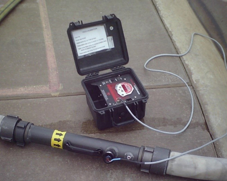
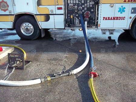
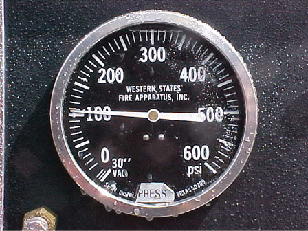
(2) A flowmeter. (3) A flowmeter connected to the supply line. (4) Note the 10-psi increments on this discharge gauge.
Determining Pump Discharge Pressure
I use the flowmeter on the supply side of the evolution within at least two 20-foot sections of three-inch hose; one is connected to the hydrant and then to the flowmeter, and the other is connected from the flowmeter’s outlet to the pumper’s intake. Again, keep the hose going in and out of the flowmeter straight to resist turbulence. Also, make sure there’s no major leak from the pumpers such as an open drain because the flowmeter will register all the water going into the pump even though the water is not coming out of the nozzle. Connecting the flowmeter to the discharge line could cause inaccuracies because it’s an added item and not part of what you are measuring.
As noted above, discharge gauges are usually designed in 10-pound increments; therefore, the final PDP determined in the flow test will not read exactly according to the increments on the gauge. For example, you may come up with a discharge pressure of 173 psi. Round the number to the closest increment on the gauge. In the world of physics, there is not an increase of one pound of pressure for every pound of pressure. In other words, if you throttle up nine psi, you might gain only five psi at the end on the discharge because pressure in any vessel that delivers water increases as the flow increases, and so does the friction loss. Therefore, even an elevation in discharge pressure and the pressure increased by the hand throttle do not always rise equally.
Preconnected Attack Lines
Preconnected attack lines are by far the most commonly used discharge hose evolution at fires. Although the PDP is generally memorized, you should still have a pump chart. Measure a preconnected attack line in place where it is connected to the apparatus. You could add the 50-foot sections of hose from the other chart; however, since the preconnect is a constant length, list it separately. If you add hose to the preconnect to get more reach, add the friction loss per 50 feet of hose to the pressure for the preconnect. You can use a flowmeter or a handheld pitot gauge for the test. Use both when testing a smooth-bore nozzle; rely on the flowmeter only when working with combination nozzles and specialty nozzles such as the vindicator and piercing nozzles.
Table 2. Flow Comparison for Stacked Tips Pumped at the Highest PDP |
||
|
Tip |
Nozzle Pressure |
Gallons per Minute |
|
2-inch |
110 |
1,060 |
|
1¾-inch |
80 |
814 |
|
1½-inch |
90 |
834 |
|
13⁄8-inch |
110 |
589 |
|
Note that the 1¾-inch tip did not change its nozzle pressure even though it was pumped as if it were a two-inch tip. The pressure for the 1½- and 13⁄8-inch tips changed, but the increase was insignificant and totally safe to use based on manufacturer specifications. You can conduct this same flow test with a combination nozzle. |
||
Fixed Master Stream
A fixed master stream is preconnected to the top of the engine by plumbing. To determine the PDP for this appliance, you must know which type of nozzle will be used—automatic, fixed combination, or stacked tip (which is a fixed gallon nozzle). The fixed master stream is capable of many variations, which are rarely used. Its high flow is used for surround and drown, medium flow is used when there is a lack of water or a smaller target, and low flow is used for miscellaneous tasks. However, there is a simple way to come up with one PDP that will work for all four stacked tips. Determine the PDP for the two-inch tip. The nozzle pressure will be 80. Let’s say the pump discharge pressure is 140 psi. No matter what tip size is used, always pump it as though it’s the two-inch tip. If the 1¾-inch tip is used, pump it at 140 psi; if the 1½-inch or the 13⁄8-inch is used, again pump at 140 psi. Table 2 shows the increase for these three sizes of tips.
With the automatic nozzle, you are not necessarily looking to change the gpm; you want to keep a good working stream by adjusting the components inside the nozzle. If you want a specific flow, you need to know what the PDP is; you will find this out through flow tests with a flowmeter. How would you figure out the PDP with any of the above-mentioned nozzles using fireground hydraulics? I don’t think it is possible, regardless of which nozzle you use on a fixed master stream.
All nonautomatic combination nozzles are flow tested exactly as the automatic. Name your flow, connect the flowmeter, and throttle up until you get the corresponding flow.
Determining the PDP for smooth-bore tips can be a little different. You can use a flowmeter if it is calibrated correctly. Calibrate it each time you use it. First, match the flowmeter with a reading from a smooth-bore tip just to make sure the flowmeter is accurate. If no flowmeters are used, the pitot gauge is your only other choice. Here again, the pitot gauge must be accurate and calibrated to remain accurate. The reading on the pressure gauge on the pitot tube represents psi; cross-reference it with the reading on a flow chart that is based on physics to get the final gpm.
Elevated Master Stream
Elevated master streams are basically like the fixed master streams, with one exception: They are mounted on aerial ladders, booms, and aerial platforms. If the unit with the elevated master stream has a pump, the flow tests used for the fixed master stream will work also for the elevated stream. Always follow the chart on the pedestal relative to flow vs. angle vs. height to make sure you have a safe operation.
There are, as you know, elevated streams on truck companies that do not have pumps. This necessitates a different method for determining PDP, which can easily be done with a flow test. Most truck companies carry the feeder hose for the ladder to feed the waterway going up to the nozzle. It’s usually 100 feet. Regardless of how long it is, calculate the friction loss of the hose on your friction loss chart to come up with the first part of the answer. The second part involves doing a flow test with a flowmeter or a handheld pitot gauge to determine the nozzle pressure for the required flow. Add the two to come up with the PDP. The third and most involved part of this flow test involves adding about 1/2 psi per foot (elevation adjustment) to the PDP. If a flow test is needed, determine the required flow through the full extension of the ladder; you may decide to go for the maximum and develop the PDP at the fully extended mode and use that throughout the extension of the ladder. The key here is, if the ladder is not fully extended, how much will the flow/nozzle pressure rise if you use the PDP for the full position? You may find that, just as in the case of the stacked tips and the combination nozzle, there is a little increase, but the PDP will still be within manufacturer recommendations. On the other hand, you may find that the operation could become unsafe if you lower the height of the nozzle to a certain point. Note this on the pump chart, and never exceed this figure. There is a possibility that you may come up with a lower flow that will work at that height but cannot be used at the maximum flow.
Portable Master Stream
The portable master stream works basically like the elevated stream without a pump. The only thing is that you don’t have to worry about elevation when calculating the PDP. Again, calculate the hose friction loss for whatever your hose evolution is to the base of the portable monitor. You already know from previous flow tests that you can pump the highest PDP/flow for any of the lower tips in the stack. If you use a combination nozzle, the same concept should apply. However, run the flow tests to verify this.
Line Extension
Line extension basically means putting hose together to reach a certain point. It is done at the fire, and the length is usually undetermined, so the hose must be counted as it is put together to form the evolution. This one’s easy. Count the hose, and reference it to the hose friction loss chart along with the nozzle pressure and any friction loss that may be in an appliance—for example, say you are using 400 feet of 2½-inch hose with a 1¼-inch smooth-bore tip and a line flowing 325 gpm = 50 (length of hose) goes into 400 (length of line) 8 times. The calculated friction loss shows the friction loss for 325 gpm and a 50 foot-line is 11 psi. Round off to the nearest increment on the gauge, which would make it 10 psi; 10 × 8 = 80 psi + 50 psi for the nozzle pressure = a PDP of 130 psi.
Gated Wye Extension
The gated wye extension is tested in basically the same way as the regular line extension except for a couple of differences. The line feeding the gated wye will be flowing up to the maximum amount of water distributed to all the lines connected to the gated wye. For this example, we will use a simple gated wye with no handlines. The scenario is 400 feet of three-inch hose supplying a gated wye with two 150-foot, 1¾-inch lines flowing 170 gpm each through 7⁄8-inch smooth-bore tips. Normally, the fireground hydraulics will have you calculate for one or two handlines flowing because, theoretically, that will make a difference when one line is shut down because of the amount of water flowing through the three-inch line feeding the wye. As long as the handlines attached to the gated wye are equal in every respect, you will have to calculate only for one: 400 feet of three-inch line. Instead of calculating once to arrive at 170 gpm (one line) and again for the other line (340 gpm for two lines), use for the higher 340-gpm flow.
You may be wondering, what would happen if one of the lines is shut down? Would the line that is still flowing rise up and become difficult to handle? The answer is, most likely not. Let’s do the calculations. First, let’s calculate the 170-gpm flow to show the difference between one line and two lines with regard to the friction loss. The friction loss for 170 gpm in a 50-foot section of three-inch hose is 1 psi. The friction loss for 340 gpm, which is for two handlines flowing at 170 gpm each, is 4 psi per 50 feet of three-inch hose. At 400 feet, the friction loss in a three-inch line flowing 170 gpm is 8 psi. For 340 psi, which is two lines, the friction loss is 32 psi. The difference between the two is 24 psi. Remember, the pressure gain drop from the engine throttle controlled by the pump operator and the actual pressure gain or drop in the hose is not equal. I would estimate only a 10 to 12 psi difference instead of the 24 psi. I recommend always pumping this evolution as if both lines are flowing. Do the flow tests, and if there is a little bit of difference in flow and pressure, especially if 2½-inch hose is used, have the firefighters try the lines to see if it makes a difference for them. I think you’ll be surprised to see that it doesn’t.
Relay Pumping
Relay pumping is probably the most complicated evolution to calculate when using fireground hydraulics. In fact, unless you know all the facts about the relay such as the flow, the length, elevation gain or loss, and the size of the hose, especially in case a second engine had picked up the relay and has a different size of hose than the original line played, you cannot use the formula. But you can use a method that is much easier and more accurate.
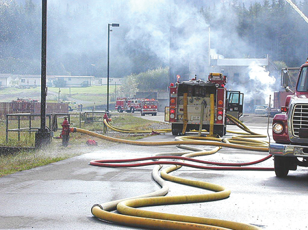
(5) Relay pumping.
Scenario
The relay line is laid. It doesn’t matter which unit does it; I prefer it is the unit that can be at the water source because the attack unit should probably be setting up its attack lines. The first pump operator, who makes the connection and is ready to start operating, radios the other pump operator that he is hooked up and ready. The other operator responds that he is hooked up and ready or that he needs a little more time and will get back to the first operator.
The unit at the water source slowly starts charging the supply line at about the same pressure as at an average hydrant—let’s say 50 to 60 psi. The goal is to charge the line as safely and efficiently as possible.
When the receiving engine gets the water to its intake, the operator lets the other pump operator know that he has received the water and can start throttling up to his target engine pressure (the pressure initially used to get a decent amount of water flowing to the receiving engine so that the operator can charge his lines and see how much more pressure/water he may need). For example, the receiving pumper is attempting to charge two 2½-inch handlines and its deck gun. The target pressure that was originally sent from the engine at the water supply was enough to support the 2½-inch handlines; however, when the pump operator tries to start the deck gun, the target pressure starts to drop significantly. To fix this problem, the pump operator calls the pumper at the hydrant and asks for more water. The pump operator at the fire determines how much more water is needed. For example, he may say, “Send me 50 more psi; I think that’ll give me enough pressure to get the deck gun going. I will get back with you.” If it looks like it’s going to be a high-flow operation from the onset, the pump operator at the fire may tell the pump operator at the hydrant to send everything he has. If he doesn’t use it all, he can tell him to lower it.
What things will stop the operator at the hydrant from sending more pressure other than the flow requirements that have been fulfilled? The maximum operating pressure of the hose may have been reached; he may have run out of water; and, at extremely high flows, an engine can run out of throttle. In a high-volume operation, the mechanism can top out and not go any further.
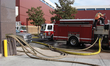
(6) The engine pumping multiple lines into the FDC.
Multistory Building with No Building Pump
Notice that I said “multistory” instead of “high-rise.” Using the term “high-rise” can be confusing based on certain components of the water-delivery system in a multistory building. There are two types of multistory structures with fire protection systems in them. One has a standpipe system that is not supplied by a building pump, and the other has a standpipe system supplied by a building pump. Explaining all that we should know about these two types of structures would take an entire article.
The first thing to keep in mind is that the National Fire Protection Association (NFPA) requires a hydrostatic test of 200 psi for water-based suppression systems (sprinkler and standpipe systems), based on a maximum working pressure of 175 psi. We determine our PDP on this basis. Another thing to keep in mind is that a firefighter must always be left at the standpipe outlet on the floor on which the handline is connected with a gate valve and pressure gauge. This stipulation is being taught in high-rise firefighting today. The position is referred to as “the mobile engineer.” This firefighter ensures that the handline gets the proper pressure to operate proficiently.
To calculate the pressure, you must know all the facts: elevation pressure loss, standpipe friction loss, handline friction loss, and the discharge lines leading from the pumper to the fire department connection (FDC). If you don’t know how many handlines are being used, the floor to which the handlines are connected, or the exact flow that the multiple handlines are delivering, you can’t use the formula.
Since the maximum pressure for these water-based suppression system is 175 psi (unless specifically designed for higher pressures and identified as such), the pump operator should pump 150 psi, as recommended by NFPA 13E, Recommended Practice for Fire Department Operations in Properties Protected by Sprinkler and Standpipe Systems.
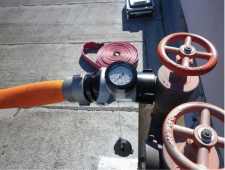
(7) A combination 21⁄2-inch valve and pressure gauge.
Multistory Building with a Building Pump
Now, we are going to put a building pump in the mix; its purpose is to create the required pressure in the standpipe system for the firefighters’ handlines.
In a multistory building with a building pump, the building pump usually gets its water from the city water main. The pump is basically like the pumps we have on the fire trucks with one exception: It does not have throttle control or revolutions per minute. It immediately throttles up to the correct pressure. The discharge of the building pump connects to the standpipe along with the FDC pipe at a point before it enters the standpipe; there is a check valve at this location. The valve prevents water from backflowing to the building pump or the FDC and back into the fire trucks. Basically, the highest pressure at the check valve is that going into the standpipe and supplying the firefighters with the required flow.
How do you determine the required flow? The NFPA currently requires that a multistory building with a fire protection system supply a minimum of 500 gpm out of the farthest of standpipe outlets—two at 250 gpm each, at a 100-psi residual pressure. This ruling came into effect in 1993. Before 1993, the rule stated that there had to be 500 gpm under the same conditions with a 65-psi residual pressure. The system pressure for this multistory is based on achieving the NFPA goal. For example, it is a 25-story building built in the 1960s, which means it has a requirement of 500 gpm at a 65-psi residual pressure and needs a 185-psi system pressure to meet the standard. Pump operators must know the building system pressure and pump it. For this building, the pump operator would hook up and pump 185 psi. The system pressure will be on the pump chart. If your city has many multistory buildings, you may want a separate chart for your high-rise properties.
It is important to get the proper PDP through your discharge lines to safely and adequately support your firefighters. Perform flow tests and calibrate the equipment used for these tests at least twice a year and before every test day.
PAUL SHAPIRO specializes in the research, development, and training of large-flow water-delivery systems and fire stream management. His extensive research and outcomes using large-diameter hose as supply and discharge lines has been published in fire service trade magazines. He has been involved with the fire service since 1981 and was an engineer with Las Vegas (NV) Fire & Rescue for 28 years until his retirement. He was awarded the department’s 2006 Engineer of the Year award. He is a certified fire instructor III for Nevada and has served on the faculty of many U.S. and international fire academies.

