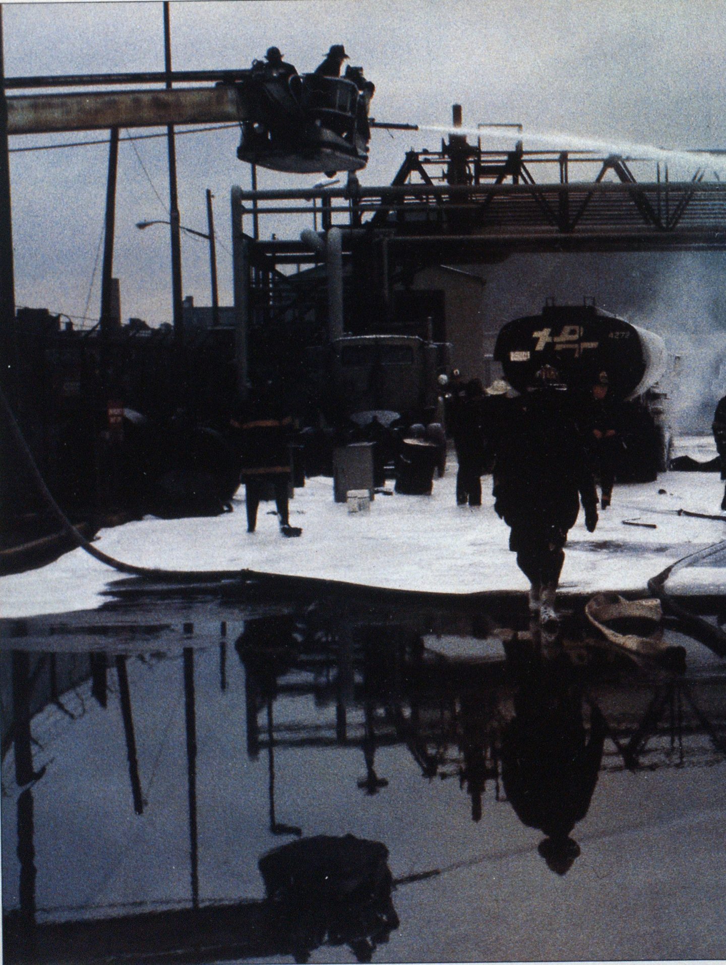


Photo by Warren Fuchs.
Foam System Considerations for Conventional Fire Apparatus
FIREFGHING TECHNIQUES
Guidelines for choosing or upgrading your foam equipment
As MORE AND MORE fire departments develop hazardous-materials response capabilities, they usually look toward foam equipment as an addition to their hazmat containment arsenal.
How should departments choose the best foam application equipment for their operations? What are some methods by which departments with existing foam equipment can enhance their operations?
There are six major types of foam systems in use on fire apparatus today: 1) premixed, 2) in-line eductors, 3) around-the-pump proportioned, 4) balanced pressure systems, 5) foam bladders, and 6) on-demand proportioning systems. Since the latter three types arc used primarily on industrial foam pumpers and crash/fire/rescue (CFR) vehicles, this discussion will be limited to the first three systems.

Photo by authors.
PREMIXED
The simplest foam system is the premixed system. Foam concentrate and water are mixed together in the booster or agent tank, ready for application. This system is easy to prepare; it’s simply mixed in the proper ratio of foam concentrate and water. For example, a 500-gallon booster tank with 6% concentrate would require 30 gallons of concentrate and 470 gallons of water.
These systems come in two types. The first is a premixed agent tank that uses air or nitrogen pressure to expel the foam solution. The containers range in size from 2V4-gallon foam extinguishers to 400-gallon systems on airport CFR units. This system is mechanically simple, and the foam solution is available immediately because you don’t have to wait for an eductor to pick up the concentrate. The air/nitrogen-expelled systems have excellent applications at racetracks, parking garages, airports, and auto accidents. The major disadvantages are that the fire vehicle must get relatively close to the scene (as hose length is usually less than 150 feet), and the discharge time is limited.
The second type of premixed system is one in which the foam/H>0 solution is premixed in the pumper’s booster tank. This is the most inexpensive system since no additional pressure system is required. Foam solution is readily available to be supplied directly into the fire pump on the apparatus. Foam solution is then available from any discharge from booster line to deck pipe. As long as the hose evolution is within the normal hydraulic limits, the pumper may be positioned a safe distance from the incident. Foam solution rate is based on the tank-to-pump flow rate.
There are drawbacks to this system:
- If the booster tank is always kept premixed, costly foam is wasted when only water is needed; furthermore, the solution will break down over a period of time.
- If the tank is premixed as needed, foam application is delayed while foam is added, and any unused foam is wasted. It is difficult to achieve a good mixture. For example, the solution may be stronger than necessary in some parts of the tank and too weak in others.
- Finally, if the solution in the tank does not extinguish the fire, you will have to start over by premixing another pumper, or drafting foam solution from a portable tank.
Drafting has proven effective for departments that are proficient in those operations. Foam flow potentials are now increased to the amount of water that the pumper can draft. Do not premix alcohol foams without consulting the manufacturer. If premixing is attempted with 1% AFFF, a uniform solution mixture in the tank will be difficult to obtain because 1 % concentrate is very’ thick.
IN-LINE EDUCTOR
The primary advantages of in-line eductors are that if adequate foam and water are supplied, sustained operations are possible, and the pumper’s remaining water flow potential can be used to apply water elsewhere, perhaps to an exposed LP tank. (Remember, the runoff water will destroy the foam blanket if allowed to come in contact with it.) If desired, enough eductors can be purchased to equal the capacity of the pump. Master stream eductor/ nozzles are available in capacities of over 1,000-gpm foam solution.
There are three methods used to place eductors on fire apparatus employing inline eductor systems. One method is to mount the eductor on the apparatus “inline” with a specific discharge outlet to create a preconnected foam line. The second placement option is in the hoseline between the pumper and the nozzle. (See Figures la and lb.) The third is the eductor/nozzle combination. These eductors are designed to provide a specific solution rate, measured in gallons per minute.
Standard high-pressure in-line eductors require high pump pressures due to the high friction loss in the eductor. An eductor inlet pressure of 200 psi is usually required for optimum performance, although satisfactory eduction will occur at lower inlet pressures. The required engine pressure must take into account this eductor pressure as well as friction loss in the hose lay and the designed nozzle pressure. Balanced-pressure in-line eductors operate at a lower required inlet pressure, allowing greater flexibility in selecting hose evolutions.
Since there is a limit to the amount of hose that can be used on the outlet of an in-line eductor, eductors mounted on the apparatus may require the vehicle to be positioned dangerously close to the incident. (Several popular 95-gpm eductors have a limit of 150 feet of 1 ½-inch hose or 300 feet of 1-Vi-inch hose on the outlet.) If foam must be pumped down a long pier to a boat fire, apparatus-mounted in-line eductors may be useless.
Installing the eductor down the line (see Figure lb) allows for longer hose lays. Since 200 psi inlet pressure is still required, select a hose diameter to feed the eductor that has a low enough friction loss to allow a margin of safety under the 250 psi annual test pressure. Again, balanced-pressure eductors have a lower required inlet pressure that helps overcome friction loss problems.
Eductor/nozzle combinations eliminate the friction loss problems because most of them operate at the standard 100 psi nozzle pressure.* However, the drawback to this is limited mobility, because the foam concentrate must be kept at the nozzle. Since mobility is not a major factor with master stream nozzles, master stream eductor/nozzles have proven very effective.
There are a few other important considerations concerning in-line eductor systems:

- The nozzle on the foam line must be matched to the eductor (for example, a (Required pressure can vary greatly depending on type of nozzle and manufacturer. )
- 95-gpm eductor requires 95-gpm nozzle setting).
- The nozzle must be kept fully open and kinks kept out of the hose, or else the eductor will not be able to pick up foam concentrate properly. High head pressures as found in ladder pipe operations have the same effect as not opening the nozzle all the way. Some in-line eductors will work with ladder pipes; be sure to consult with the manufacturer before you buy one for this purpose.
- Since water must be flowing to begin the venturi action in the eductor, it will take time to get foam solution from the nozzle (usually 15 seconds to a minute depending on the length of hose from the eductor to the nozzle). The nozzle operator should discharge off to the side until good foam arrives at the nozzle. Failure to do this could spread a fire. If your operations require switching from foam to water and back, you should consider bypass eductors that allow the changeover with the turn of a valve.
One final tip —when large quantities of foam concentrate will be used, use a washtub or a small drafting tank to hold the concentrate. This eliminates the need to switch the eductor pickup tube from can to can. (A 250-gpm eductor will empty a five gallon can of 6% concentrate in 20 seconds!) (See Figure 2.)
AROUND-THE-PUMP PROPORTIONER
This system uses an eductor to introduce foam concentrate to water, but instead of being mounted in-line with any one specific discharge or hose line, the concentrate enters the intake side of the pump, making it available to the entire discharge manifold. (See Figure 3.)


The around-the-pump proportioner system allows the officer to use any hose evolution desired as long as the combined gallonage does not exceed the foam solution capacity of the system, litis is not necessarily equal to the pumper’s capacity. One common system has a solution flow capacity of 200 gpm with 6% concentrate and 400 gpm with 3% concentrate. The extra pumping capacity could not be used because the entire discharge capacity is “wet” with foam, and exceeding the foam solution capacity would result in weak foam.
Around-the-pump proportioned are available in flow capacities that match any pump capacity; just make sure you know the limits of the one you are buying. Most of these systems are installed in the pump’s plumbing at the time of purchase; however, external systems are available that can be installed on any existing pumper at a reasonable cost.
Because the foam concentrate is introduced to the intake side of the pump, intake pressure must be regulated. Excessive intake pressure will stop the venturi effect and foam will not be picked up. Most manufacturers recommend that intake pressure be maintained at or slightly below 10 psi.
This is very difficult to achieve due to fluctuations in the water distribution system. When low foam-solution flows (perhaps at 150 gpm) are used and your pumper is being supplied with large-diameter hose from a strong hydrant, maintaining 10 psi intake pressure can be nearly impossible. Also, there is no margin of safety if water-main pressure drops suddenly.

FOAM SYSTEM CONSIDERATIONS
Electronic around-the-pump proportioned do not require a specific intake pressure but instead require a difference of 80 or more psi between the pressure reading on the compound gauge (intake presure) and the working pressure (discharge gauge). These are much easier to work with. Electronic proportioners do not require a constant readjustment of the metering valve every time the flow rate changes.
Several departments have overcome the intake pressure regulation problems by running the supply line directly into the booster tank. This is much easier than trying to maintain 10 psi intake; however, there are some potential problems. Even if your proportioner’s foam solution flow rate equals your pumper’s capacity, the actual flow rate is limited to your tank-topump flow rate. It is essential that the supply line is secure; just sticking it in the top of the tank is unsafe. Since good tactics dictate that the pumper be placed uphill of a spill or fire, you must ensure that overflowing tank water does not come in contact with the foam blanket. One way to avoid this is to install a diverter line in the tank overflow pipe.
As with in-line eductors, it takes time to get good foam solution to the nozzle; therefore, the nozzleman should discharge off to the side until good foam is obtained. Finally, around-the-pump proportioners are not affected by elevated nozzles and are an excellent choice for ladder pipe operations.
The accompanying chart (Figure 4) summarizes the advantages and disadvantages of each system discussed. There is no one best system. Now that you know the merits of each, you can choose the one that’s best for your department.*

Not recommended with alcohol foams—extremely difficult to obtain homogeneous mixture.

