FIRE FLOW TESTING
Fire flow testing is a relatively easy procedure. To conduct a fire flow test, the following equipment is needed:
- two fire hydrants with at least one 2 1/2-inch nozzle butt on each.
- a map of the water supply piping serving the hydrants.
- pitot gauge.
- 2’/2-inch cap gauge with bleedoff cock.
- hvdrant wrench.
- ruler accurate to ‘/Winch.
- pad of paper and pencil.
To conduct a flow test, follow the steps below in numerical order. (For safety, always stand behind an open hydrant.)
1) Select the two hydrants nearest the property in question; designateone as a “pressure hydrant” and the other as a “flow hydrant”
2) Sketch the location of the hydrants and the mains supplying them.
3) View the area around the flow hydrant to ensure that precautions are taken to avoid property, pedestrian, and vehicular damage from discharging water.
4) Take one 2’/.-inch cap off the pressure hydrant and tighten its other caps.
5) Attach the cap gauge to pres| sure hydrant.
6) Open the pressure hydrant tully and bleed off trapped air.
7) Record the pressure (psig) shown on cap gauge.
8) Remove one 2’Winch cap from the flow hydrant and tighten its other caps.
9) Measure the orifice size (inside diameter) to the nearest Vu inch.
10) Feel the interior of the nozzle butt where it is attached to the barrel and compare it with those pictured on the opposite page, bottom, to determine its discharge coefficient.
11) Open flow hydrant fully.
12) Wait for constant “clear” and consistent flow (no trapped air) and then place pitot tube in stream following the placement criteria: Place the orifice on the pitot blade in the center of the stream and place the edge of the pitot blade one-half the diameter of the nozzle butt away from the nozzle butt. Take the velocity pressure reading (psig) and record.
13)Take a second pressure reading (residual pressure) on pressure hydrant while pitot reading is being
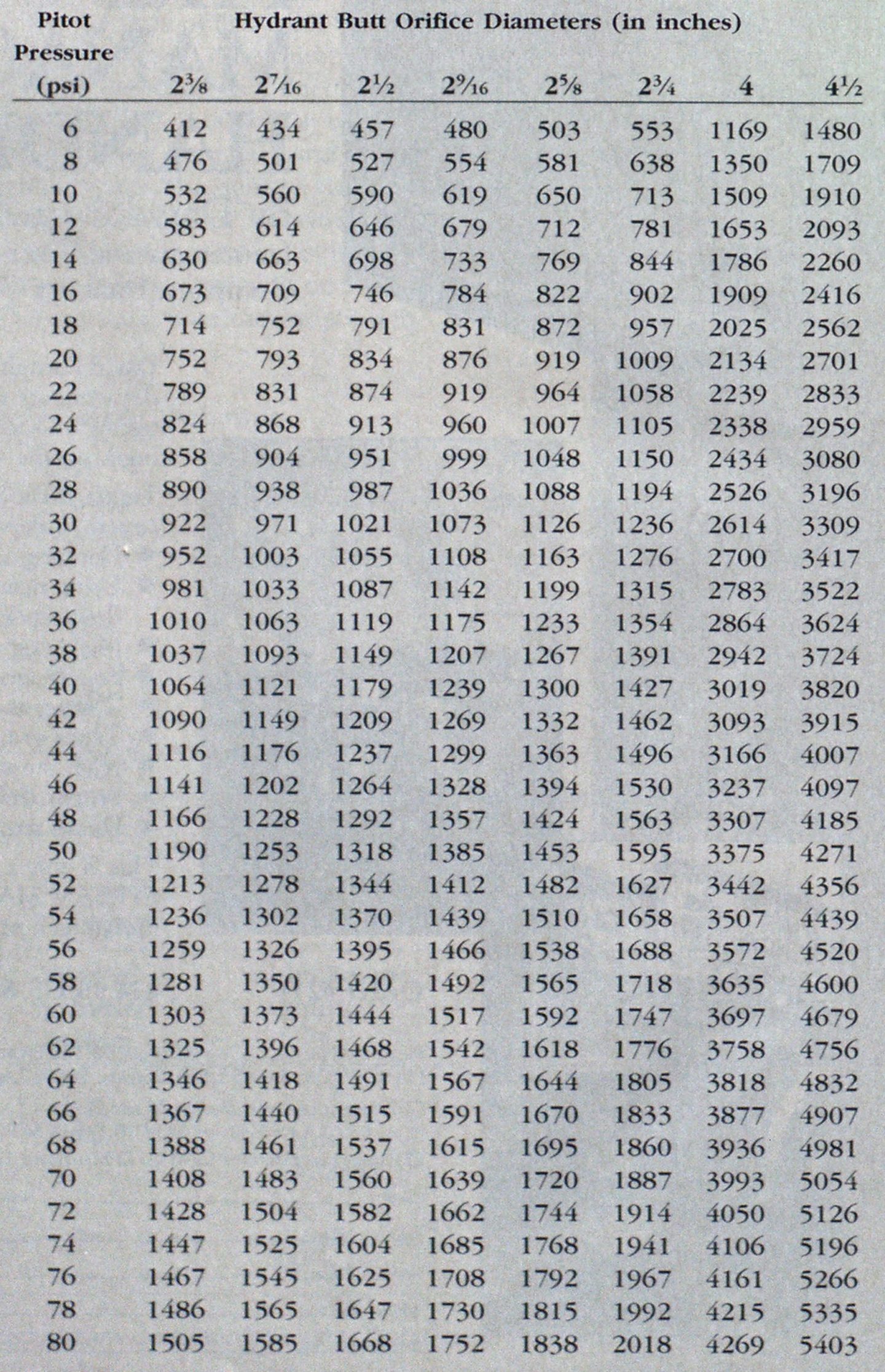
Pitot Gauge Conversion Chart


taken on flow hydrant and record.
13a) Additional step to increase accuracy (if necessary): If the pressure drop of the residual pressure on the pressure hydrant is less than 25 percent of the original static pressure, shut down the flow hydrant and open two 2’/2-inch nozzle butts and take a new set of pitot readings. Continue opening 2’/2-inch nozzle butts on additional flow hydrant(s)
ntil the 25 percent figure is reached. (A pressure drop of at least 25 percent is a commonly accepted practice for these tests.) Remember that each open nozzle butt represents flow—-you must record pitot readings for every nozzle flow to determine the total water flow.
14) Slowly close both hydrants (at the same time open bleed-off cock on pressure hydrant to allow for proper drainage).
15) Verify that both hydrants have drained fully by making sure water has passed below the level of the “steamer” (pumper connection).
16) Replace caps and tighten.
After you have performed the flow test and have recorded the information, the next step is to calculate the actual flow and plot the data.
To calculate the actual flow for each hydrant butt, first convert the velocity pressure reading(s) on the pitot gauge to gallons per minute byusing the pitot gauge conversion chart (far right). Find the hydrant’s pitot pressure reading on the left side. Next move along die hydrant butt orifice diameter columns until the correct hydrant butt size is reached. Record the flow specified. Finally, multiply this flow by the nozzle butt discharge coefficient (determined earlier) to find the final fire flow for that nozzle butt.
If you opened more than one hydrant butt, add all of the “converted” flows together for each residual pressure reading. This is expressed in gallons per minute at some specific residual pressure.
For example, let us say fire flow testing was conducted at a paper processing plant and two nearby hydrants were selected. The static pressure in the “pressure hydrant” was found to be 80 psi. A pitot gauge reading from the one open 2 Vi-inch hydrant butt (with a 0.8 discharge coefficient) on the “flowing hydrant” was 45 psi and the residual pressure was 60 psi.
With the pitot reading pressure, the flow’ rate from a 2‘/2-inch hydrant butt is found; for the pitot reading of 45 psi the flow is roughly 1,250 gpm. This is then multiplied by 0.80 to find the actual flow’ of 1.000 gpm.
Next, plot the static and residual pressures and corresponding flows on Q semiexponential paper (see graph above). Remember, a static pressure reading means 0.0 gpm flow’.
Finally, draw a straight line through the points and extend the line to 20 psi. This is the available water supply line (curve).*