By Ron Zawlocki
You arrive on the scene of a trench rescue with the technical rescue team. The incident commander has been desperately waiting for your arrival. In the briefing, the incident commander (IC) tells you that two workers are trapped in a deep intersecting trench and that you are in charge of shoring. When you get to the trench and make your assessment, you find that this is a 12-foot0deep T-trench that is six feet wide. One corner of the trench has caved in, leaving a huge void. You have trained on shoring T-trenches, but they always have been in passive soil with both corners intact, and they have never been this wide or deep. This is heavy, wet, and unstable soil. You feel that these conditions could easily create the lateral forces associated with C-60 soil. You are the “trench guy” and will be making important decisions today.
Your plan is to implement as much as possible of the shoring technique you learned in class. However, there are some major differences here. The wales that you will be using today will have to span 10 feet or more instead of eight feet, the spans that you trained with. Additionally, you will be back-filling the corner void with multiple (stacked) low-pressure air bags. The T-trench shoring that you learned in class did not address large corner cave-ins. You know that your team will be able to put this plan in place, but you have serious concerns about the strength of this shoring system. Is the capacity of the six-inch by six-inch wale at a 10-foot span more than the soil force that it will be set up to resist? Will the stacked air bags be stable enough to resist the forces transferred from the opposite walls through the struts–in short, is the ultimate strength of your shoring system design stronger than the potential forces of the trench walls? Twice as strong seems reasonable, but what is the minimum requirement? You had questions about this during your trench technician class, but the instructor kind of “side stepped” them. It sure would have been nice to have been taught a method to calculate safety factors for different shoring designs instead of the “no questions allowed” rote teaching method that you were given.
When the shoring is complete, the members of your team turn to you and ask, “Can we get in and dig these guys out?” They are asking you if it is safe. They deserve to know that answer. Their families and friends deserve to know that answer. Do you know (for sure) that the shoring system is stronger than the soil force? Well, haven’t the instructors you learned this from tested the design to make sure it can resist the forces of the soil you expect to install it in? Haven’t the rescue equipment manufacturers tested this system to see how it performs in a trench? Isn’t there a performance standard (National Fire Protection Association, ANSI, or Occupational Safety and Health Administration) for trench rescue shoring that requires a system to be strong enough to resist the lateral forces of soil? Unfortunately, the answers to these questions are a resounding “NO.”
Trench Shoring History
Trench recue shoring gets its roots from the underground construction industry. The basis for the use of traditional sheeting and shoring (a fading construction shoring method) is to prevent movement of the soil. This can be done by construction workers as a result of being able to start shoring soon after (and sometimes during) the excavation process. When you can stabilize a wall before it moves significantly (large fissures or cave-in related voids), some construction-related theories can be applied. Empirical evidence (witnessed results) suggests that theories like “soil arching” and “pressurization zones” created by strut activation forces have merit when soil walls are intact and not active. However, after the soil has begun to move and has created voids in the wall(s), these theories become questionable at best.
Very little testing and research has been done on trench rescue shoring. Data that compare the performance of rescue shoring systems and lateral soil forces do not exist. Standards, tabulated data, and engineered designs exist for the underground construction industry, but construction shoring and rescue shoring are not the same. In the only published study on “trench rescue shoring,” Dr. Marie LaBaw concludes: (1) There is a lack of engineering analysis for trench rescue shoring and (2) underground construction shoring and trench rescue shoring are significantly different.
Clearly no quantitative value can be assigned to construction-based theories when soil is active or has caved in. As a result of the many differences between rescue shoring and construction shoring, trench rescue shoring systems must be designed and tested to resist “worst-case scenario” soil conditions, which include the following:
1. Soil that has not been shored (or has not been properly shored) prior to its becoming visibly active.
2. Soil that has caved in, leaving voids in the wall(s). The walls are no longer intact or “monolithic” in appearance. Soil walls will act more like damaged unreinforced masonry rather than reinforced concrete walls.
3. Visible signs (sloughing, raveling, widening, fissures, for example) may or may not be apparent, but the soil is considered to be unstable.
4. Portions of vertical or “near vertical” walls exist.
5. Pressures in this type of soil conditions are estimated at 60 pounds per cubic foot.
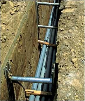
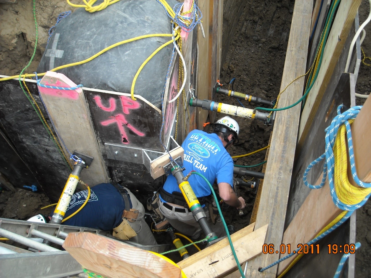
Photo 1

Photo 2
Shoring practices and theories used for freshly dug (passive soil conditions) like those seen in photo 1 cannot be counted on to perform the same after the soil has started to move (become active) as seen in photo 2. Construction shoring and rescue shoring are different. (Photos courtesy of author.)
Shoring Standards
For several years, a group of rescuers and professional engineers have worked together to enhance the shoring and stabilization capabilities used at structural collapse rescue incidents. The group continues to make improvements based on gains from experience, testing, and technology. The results are published by the Department of Homeland Security’s in the Field Guide for Building Stabilization and Shoring manual. The testing method used measures the strength of the shores by setting them up in a position of function (a building collapse replication) and subjecting them to vectors (force magnitudes and directions) that would be developed by a damaged structure. By taking the shore to failure (breaking it,) the ultimate strength can be established and compared to the force it was designed to resist. That comparison can provide a “safety factor” that validates the shore’s ability to keep the building from falling down on the rescuers. Improved safety factors can be achieved by testing modified versions (nail patterns, bracing, materials, and so on) and comparing results. The published field guide has become a benchmark for structural collapse rescue instructors. The shoring designs and recommended practices have become a consensus standard for the fire and rescue service.

Photo 3

Photo 4
Subject matter experts from the structural collapse rescue discipline recognized that OSHA-compliant shoring (photo 3) for the construction industry did not address the differences (purpose, scope, and magnitude) of damaged structures that included trapped or injured victims (photo 4).
Unfortunately, trench rescue shoring has no such guideline. Very few shoring system being taught today have actually been tested to failure in their position of function (in a trench, not on computer software). True safety factors have not been established. Quantitative results have not been established to sort out myths, folklore, and the misplaced applications of construction-based, soil-retention methodology. Without a guide and a consensus standard, trench rescue instructors continue to pass along shoring techniques that have little or no scientific validation.
Backyard Tests
The MUSAR Training Foundation has conducted a series of destructive tests on trench shoring components (panels, wales, and strut equipment) as well as complete trench rescue shoring systems. We recognize the fact that more precise instrumentation would be desirable and that more tests are needed to obtain replicable results. Until that occurs, the precision of our “backyard testing” results should be considered. It is our sincere hope to gain the support of subject matter experts, rescue equipment manufacturers, and professional engineers to enable trench rescue shoring to duplicate the achievements of the structural collapse discipline.
With that said, we have used two types of tests to evaluate the strength of shoring components and systems in their position of function (in the trench). In both types of tests, the magnitude of the force delivered is comparable to the soil pressures of C-60 soil. The direction of force in both tests is lateral, replicating the movement of a wall into the trench.
A Type I test takes a shoring component to failure by using air bags as the force. An air bag is placed directly behind the component being tested, creating a lateral force. Load cells are used to record the forces applied and to determine the maximum forces applied at the point of failure (component strength). These tests are conducted in the trench or excavation, and the tests show how the component reacts to force in its position of function (i.e., in a trench, not in a laboratory). Type I tests are also used to get a “quick look” at system strengths. If a system design can resist twice the force that 60 pound per cubic foot (pcf) soil could apply, that system is considered for further (Type II) testing.
A Type II test is used to create force on the shoring system rather than on an isolated component. The application of forces can be controlled to create higher forces near the bottom of the trench to test the system’s ability to resist soil pressures. This test is done by digging a narrow trench parallel to the shored trench. Air bags are placed into the narrow “parallel trench.” When the air bags are pressurized, a section of soil wall is moved, creating a lateral force onto the shoring system. In a Type II test, the force more closely replicates the forces of an active (moving) soil wall and its distribution into the shoring system. Video footage of some of the Type I and Type II tests can be seen on YouTube by searching MUSAR Trench.
Game Changers
The load cells that we use are scaled to measure force increments of one thousand pounds. Results in the hundreds or less pounds range are not obtainable with these instruments. As a result, we cannot provide results that are accurate to a pound of force. Nonetheless, there have been results from our testing that have been so dramatic that they have caused many trench rescue teams to make changes in their equipment and tactics.
1. Panels. A variety of panel/strongback configurations are used by trench rescue teams across the country. Contrary to popular opinion (folklore), Dr. LaBaw’s testing revealed that strongbacks and panels each have significant structural value and have a significant effect on distributing the strut load to a larger area of trench wall. Tests conducted by the MUSAR Training Foundation have shown the ultimate failure strength of ¾-inch Finnform that is glued and screwed to a 2-inch by 12-inch strongback can resist in excess of 30,000 pounds of force (distributed) between struts that are spaced at four feet on center. The same sized Finnform and panels that are held together by bolts and nuts failed at less than one-half of that force.
2. Wales. Many trench rescue teams use 6-inch by 6-inch timers as wales. A common span (between struts) for “rescue wales” is eight feet. MUSAR tested several 6-inch by 6-inch timbers with struts spaced at eight feet and found a very large variance in breaking points (between 7,000 and 18,000 pounds of force). The most “common” failures occurred at about 14,000 pounds of force. When comparing the “common” strength to the potential force of C-60 soil, you will find that a 6-inch by six-inch is capable of resisting soil forces in only very shallow trenches. For that reason, OSHA requires much larger timbers for construction shoring C-60 soil. Tests conducted on 7-inch by 7-inch laminated veneer lumber (LVL) showed much smaller variances in strength between samples (41,000 and 48,000 pounds of force), and they were consistently two to three times stronger than 6-inch by six-inch timbers.

Photo 5. Seven-inch by 7-inch LVL beams used as walers are up to three times stronger than 6-inch by 6-inch timbers.
3. Excavation Raker Shores. The placement, direction, and magnitude of forces created by soil walls can be significantly different than created by structural walls. In an effort to replicate forces found on excavation walls, MUSAR tests created forces at both the top and bottom of the wall. Raker shores consistently broke at the point that connected the upper and lower struts. Working with Paratech Rescue Inc. an angled base plate was developed which more than doubled the strength of the “excavation raker” and established an acceptable safety factor.

Photo 6. The angled base plate more than doubled the strength of the “excavation raker” system. Demands, conditions, forces, and equipment common to trench rescue shoring are different from those when the construction industry standard was developed.
***
In the past decade, the fire service has seen dramatic changes in equipment and practices that have come about as the result of scientific testing and advances in technology. Structural collapse and rope rescue both have used scientific testing and analysis to enhance rescuer safety. In 2009, Dr. Marie LaBaw stated, “There has traditionally been a lack of engineering analysis of technical rescue systems, including trench rescue shoring. As education and technology increasingly pervade the technical rescue industry and the fire service, the potential to research, evaluate, and recommend changes to existing rescue systems is becoming a reality.” Unfortunately, to date, the fire/rescue service has made no movement to research, evaluate, or recommend changes to trench rescue shoring practices. As we look away from science, testing and technology trench rescue shoring remains “our dirty little secret.”
BIO
Ron Zawlocki began his fire service career in 1974 with the Detroit Fire Department. He retired from the City of Pontiac Fire Department in 2007 as a battalion chief. He continues to serve as a rescue team manager with MI-TF1 and is the trench rescue course manager for the MUSAR Training Foundation/Michigan State University fire/rescue programs.

