BY JEREMY RIFFLARD
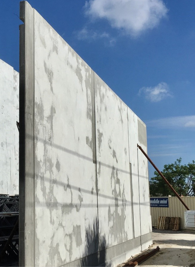
Modern construction has shown an increase in using concrete “tilt-up” wall construction. Typically, this is a cast-in-place wall that a crane raises into place; it is held with tormentor poles until it is bolted into place.1 These strong, heavy structures are typically 20 to 50 feet high and are secure until fire, extreme wind, an explosion, or other forces confront the connections. Have you ever thought about how you would stabilize a leaning, disconnected, 40-foot-high concrete wall?
Natural or man-made disasters can severely damage these concrete structures. The damaged structures may have walls bowing outward or detached connections between the wall and the roof. Either may be an indication of the potential for an outward collapse of these heavy walls. Collapsing walls have injured and killed civilians and firefighters. The best protective action is to designate a no-entry collapse zone that is a minimum distance of 1½ times the height of the wall away from the structure.
The Federal Emergency Management Agency Structural Collapse Technician course recommends the best approaches in the following order for hazard mitigation: Avoid the hazard, limit exposure to it, remove it, and then shore it. If it is not possible to avoid the “at-risk” structure because of rescue operations, postincident investigations, or other reasons, stabilize the areas of weakness with emergency shoring. The United States Army Corps of Engineers has developed a Field Operations Guide (FOG) on techniques to construct emergency shores. Updates to the FOG are often done annually and posted on DisasterEngineer.org.2 The changes are available on the Web site for free download. Included are specifications for the double insertion point raker shore.3
One type of emergency shore used to stabilize an exterior wall is the raker shore. The traditional raker shore provides support against an outward leaning or weakened structural wall by creating a triangular support consisting of a wall plate that is attached to the leaning wall, a horizontal sole plate positioned as low as possible over rubble or on the ground, and a longer diagonal connection known as the “raker.”
The raker extends from the sole plate upward to meet with the wall plate. The raker meets the wall plate at the insertion point (IP), which is usually at the level where the upper floor meets the wall. The IP can be as much as 24 inches below the second floor.

(1) A series of tormentor poles are stabilizing a 40-foot-high tilt-up wall. (Photos by author.)

(2) A single pole on each side is stabilizing this wall. This wall section is lacking support and presents a collapse hazard to responders.
Double Insertion Point Raker Shore
In 2016, the FOG added the double insertion point raker shore, a taller raker shore with two insertion points on the wall plate. One raker extends down from each insertion point to the sole plate. This is an excellent shore that can be used to stabilize a tilt-up, heavy concrete wall.
Miami-Dade (FL) Task Force 1 Structures Specialist Enrique Perea says that the double insertion point raker adds stability and bracing to prevent the raker’s lumber from buckling. When these structures are exposed to fire, the metal roof trusses can expand and push the walls outward, breaking some of the connections holding the wall in place. Because of the increased wall height, floor loads, and weight of the tilt-up panels, the typical single insertion point raker may be ineffective for shoring such structures. The two insertion points involved in each double raker shore allow for better lateral load distribution to the ground and a higher, more stable insertion point. The double insertion point rakers can terminate into a solid sole plate or two individual troughs if debris or sloping ground is present. Whenever possible, consult a certified structural engineer who specializes in collapse operations to verify the stability of the shoring.
The current FOG gives step-by-step instructions for the construction of the double insertion point raker shore with a solid sole plate. I will discuss the assembly of this shore at a 45° angle.
You can assemble the double insertion point raker shore in place against the structure, or you can fabricate it in a “cold zone.” Since it is safer to assemble it as far away as possible from the potential collapse zone, I prefer to assemble the shore a distance of two times the height of the leaning wall.
Construction
Begin the construction by toe-nailing the sole plate onto the wall plate. Cover the connection with a full gusset plate. Drive eight 8d nails into the wall plate, verify your 90° angle using the “3-foot-4-foot-5 foot” method, and then add five 8d nails into the sole plate. If you are using duplex nails, these nails should be flush since a midpoint brace will go across this connection in a later step.
Use a wood bit to drill at least three holes through the wall plate for a 45° raker or five holes for a 60° raker. Make the holes large enough for rebar or lag bolts that may be used to secure the shore to the wall. Pin the wall plate to the wall before you pressurize the shore. You can also do the drilling in the cold zone to reduce your team’s exposure time to a potential wall collapse.
ALSO
HAZARDS OF PRECAST CONCRETE WALL PANELS
Find the raker angles and return cut as you would for the standard raker shore. Use a miter saw, a speed square, or another technique to create your angle on the raker. Allow for the return cut, which is where the raker meets the wall cleat or sole cleat.
The two rakers are toe-nailed into the wall plate at the two insertion points and flush against the wall cleats. Make sure this connection is tight. Cover the top IP joint with a full gusset plate and nail eight 8d nails through the gusset into the wall plate. Verify your angle with a speed square; then add five 8d nails into the raker.
Some rescuers prefer using only one nail in the raker at this point and finishing the five-nail pattern when it is installed. I have seen the double raker come apart because of the weight of the long lumber when it is carried over to the wall. That’s why I prefer to add all the nails in the full gusset.
The lower raker IP is covered with a horizontal 2-inch × 6-inch that is nailed into the wall plate with five 16d nails and extends across both rakers. Put only one 16d nail into the rakers since the nail must be removed before pressurizing the shore.
The 2-inch × 6-inch midpoint brace traverses from the wall plate/sole plate connection covered with the full gusset plate across the two rakers. Hammer five 16d nails into the 2-inch × 6-inch and one 16d nail into each raker.
Flip the raker over and mirror the gussets, the diagonal, and the horizontal brace. I put the sole cleats and sole full gussets on after I pressurize the shore.
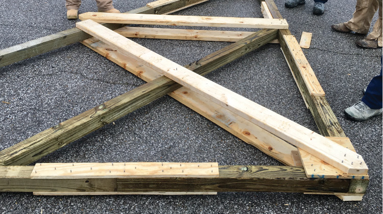
(3) The double insertion point raker is assembled in a safe area away from the collapse zone. Note that the wall plate, sole plate, and longer raker were spliced together since the lumber was not long enough to meet the length requirements. Splicing consists of butting the joint and using a 36-inch × 3½-inch cut of ¾-inch plywood and eight nails on each side of the joint using a US&R-approved nail pattern.
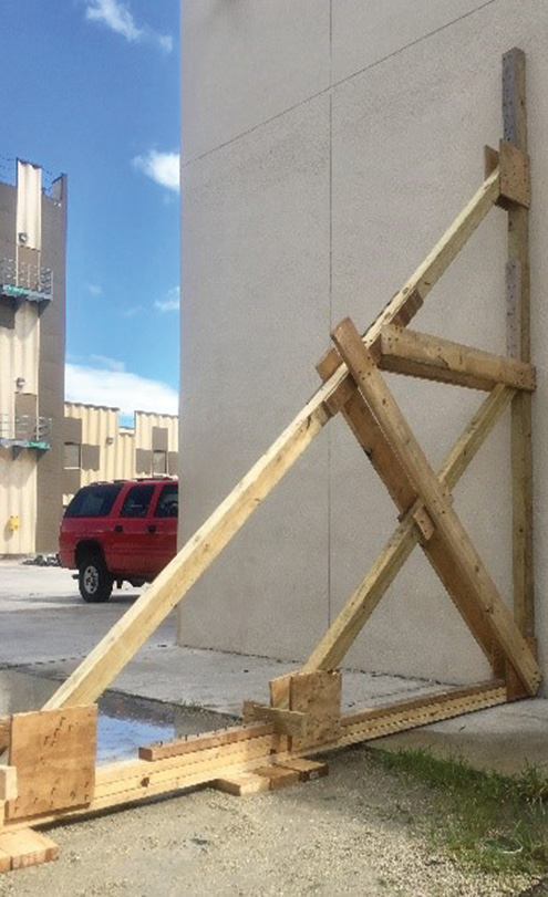
(4) The double insertion point raker shore is installed against the wall. Notice the two insertion points on the wall plate.
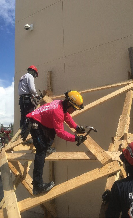
(5) Raker shores are always built in pairs. After the second raker was brought against the building, rescuers are lacing the two shores together with horizontal and diagonal bracing.
Installing the Double Insertion Point Raker Shore
Now you are ready to take the trough, cleats, wedges, and 6-inch × 6-inch anchor and install your raker. Have your team carry the raker to the installation location. Flush the sole/wall plate connection to the wall. Secure the 6-inch × 6-inch anchor into the soil or pavement. Keep a one-inch gap between the shore and the anchor for wedges, and charge the sole plate.
Secure the wall plate to the building with rebar or lag bolts. Remove the single nails you drove into the raker, which will allow your shore to flex toward the wall during the next step. On the sole plate, leave a one-inch gap between the back of each raker cut, and attach the sole cleat. After the cleat is in place, pressurize the shore with 2-inch × 4-inch wedges until the wall plate has good contact. Fill any gaps in the wall plate with shims.
At a minimum, raker shores should always be installed in pairs. This creates a more stable, Class 3 shore. Install the second raker shore about eight feet from the first shore. Lace the two raker shores together with a combination of horizontal and diagonal 6-inch × 6-inch braces. The FOG has the patterns for the lacing.
A common issue with the double insertion point raker is that the lumber you possess is not long enough to construct the components, specifically the wall plate, sole, and raker. You will have to splice to create longer lumber. Cover the joint of the two connected 4-inch × 4-inch lumber with two 36-inch × 3½-inch strips of ¾-inch plywood. Center it over the splice joint. Put eight 8d nails into each side of the joint.
A double insertion point raker shore adds additional resistance to buckling, as two rakers transfer the weight of the building into the sole or ground. Double insertion point rakers add more resistance to buckling, which makes them a great choice to use on tilt-up concrete walls. This shore is typically taller than a standard raker shore and will require greater lengths of lumber. If your lumber is not long enough, your team must splice lumber together in a manner consistent with the FOG.
Construct your double insertion point raker shores as a pair to create a stable, permanent Class 3 shore. Since it is not common to build this type of shore, practicing the fundamentals will keep your team proficient in shoring. Your team may be called to stabilize a structure before advanced interior operations can begin. Be prepared for the challenge by adding this shore as another tool in your toolbox. Emergency shoring is installed for our safety during a rescue. Be knowledgeable and operate safely.
Endnotes
1. Havel, Greg. Fireengineering.com. (September 2012). “Construction Concerns for Firefighters: Precast and Tilt-Up Concrete Walls.” .
2. Disasterengineer.org: The FEMA US&R Sub-Group. Resource. http://disasterengineer.org/.
3. US&R Structures Specialist Field Operating Guide, Edition 8.2. (September 2017). “Constructing Lateral Shoring Systems: Double Raker.” 3-23, 3-24. https://bit.ly/2y6teoc/.
JEREMY RIFFLARD presented on swing-stage scaffold rescue at FDIC International 2019. He is the lead instructor for the structural collapse technician training program and the lead instructor for the scaffold rescue program at the Coral Springs (FL) Regional Institute of Public Safety. Rifflard is also the program manager for his company TechnicalRescueTraining. For the past 20 years, he has been the subject matter expert with L2 Defense for first responders and military urban search and rescue exercises. He is a captain with the Fort Lauderdale (FL) Fire Department and a rescue team manager for the FEMA Urban Search and Rescue Team FL-TF2. Rifflard’s most recent task force deployments were to the Haitian earthquake and the 2018 Hurricane Michael in Mexico Beach, Florida.

