
By Clay Magee
Photos by author except as noted
Standpipe 101
The late Andy Fredericks once said: “Standpipe systems are like a big black hole. You put water in one end and hope that water will come out the other end.” That is the God’s honest truth when it comes to fire protection systems. Standpipes are one of the most misunderstood aspects in firefighting for most of the fire service. Unless you work in New York City, Chicago, or other major metropolitan cities that fight fire in high-rise or standpipe-equipped buildings on a regular basis, chances are you know little about these systems. These systems are complex: Anything that can go wrong most likely will go wrong.
I’ve been fortunate to listen to the who’s-who in standpipe and high-rise firefighting world multiple times: Bill Gustin, Dave McGrail, Ray McCormack, John Ceriello, Dennis LeGear, and so on. These experts mostly work in different regions of the country and all operate somewhat differently. However, so much of standpipe firefighting is the same no matter where you go, as long as that is an experienced, standpipe-using fire department. Much of the country is inexperienced in standpipe firefighting, but standpipe-equipped buildings are becoming more and more common throughout suburbia. What follows is a four-part series overview of standpipe systems, the National Fire Protection Association (NFPA) codes that regulate them, equipment selection, hose loads, and even some thoughts about pumping these systems. These are building blocks: You will see how knowledge of the systems and their requirements leads to equipment selection, and so on.
(1) John Nanninga, Houston Fire.
RELATED FIREFIGHTER TRAINING
Andy Fredericks: STANDPIPE SYSTEM OPERATIONS: ENGINE COMPANY BASICS
STANDPIPE SYSTEM OPERATIONS: THE STANDPIPE KIT
Gustin: Standpipe Operations: Preparation
McGrail and Tracy: Standpipe Operations: Facts and Fiction
Understanding Standpipes
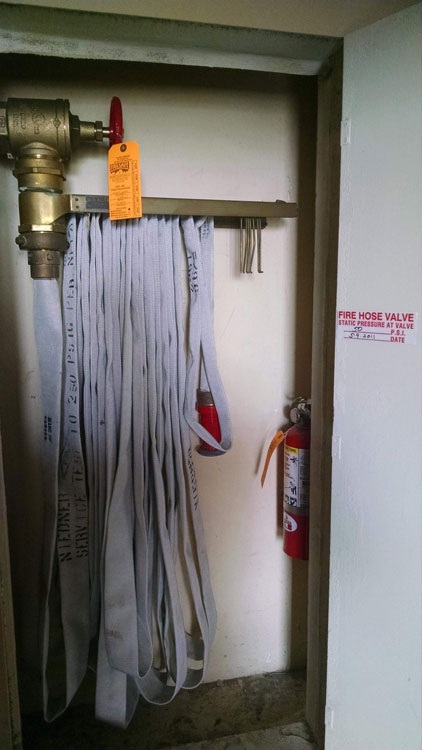
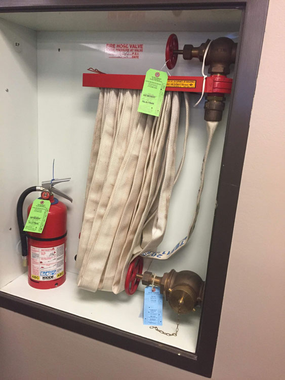
The first step to understanding standpipes is the technical data, the classes of standpipes, the types of standpipes, and the related NFPA standards and recommendations that go along with them. This is the first building block. These standards and the information that they contain drive all decision making in specifying and purchasing hose, nozzles, and equipment. Not only do they guide the development of your equipment, it also guides how you pump these systems. There are three classes of standpipes. Class I standpipes are for trained firefighter use. They have a 2 ½-inch outlet and are capable of flowing a minimum of 250 gallons per minute (gpm) from each individual outlet. Each riser should be capable of flowing 500 gpm. The pump should be capable of providing 500 gpm from the first riser and 250 gpm from each additional riser. The pump should be capable of providing this for at least 30 minutes. Class II standpipes are for civilian use. These are the hose cabinets that you see in older buildings (Photo 1). They are being phased out and most jurisdictions have removed the occupant use hose. They do not have the same standards as Class I or Class III standpipes. They have a 1 ½-inch connection with single jacketed hose with a twist off type nozzle. They are only capable of producing 100 gpm. These should not be used by firefighters. The third class, Class III (Photo 2), meets all the same criteria as Class I however, they have a 1 ½- and a 2 ½-inch connection. You may find these types of connections in a wall cabinet and the occupant use hose has been removed. It is important that if you use 1 ¾-inch hose, do not use the 1 ½-inch connection; use the 2½-inch connection with a reducer or pig tail. Remember, Class II connections have limited pressure and limited gpm.
(2) John Nanninga, Houston Fire.
There are two main categories of standpipes, wet and dry. Wet systems are either automatic wet or manual wet. Automatic wet systems keep water in the standpipe system at all times and have a fire pump capable of providing the needed pressures. Manual wet systems keep water in the system at all times but are not backed up by a pump. A combination manual wet standpipe and sprinkler system may have sufficient pressure to supply sprinklers without a pump or need a relatively small pump to supply sprinklers but will not adequately supply hose outlets.
The fire department would have to supply the fire department connection (FDC) to have pressure on its attack lines. Automatic systems are the most commonly found systems in high-rise buildings, but it is up to each department to perform pre-incident planning and building inspections to identify any abnormal systems. Automatic and semi-automatic dry systems keep air in the standpipe. Automatic systems keep air under pressure. If the standpipe outlet valve is opened, it opens a valve allowing water to fill the system. Semi-automatic systems have unpressurized air. Water is introduced via a dry pipe valve that must be activated manually. The two dry systems above have a permanent water supply. Finally, the manual dry system has unpressurized air in the system and has no fire pump or water supply, making it mandatory for the FDC to be used before fire attack can be made. These are common in parking decks in areas that are prone to freezing. They are also notoriously unreliable due to their accessibility to vandals. Caps can be missing and valves open with no indication until you charge the system and water spills out of multiple unused outlets and you are unable to build pressure in the system.
There are two main NFPA documents that pertain to standpipes. The first and most well-known is NFPA 14, Standard for the Installation of Standpipe and Hose Systems. The second is NFPA 13E, Recommended Practice for Fire Department Operations in Properties Protected by Sprinkler and Standpipe Systems. NFPA 14 is a design and installation standard but it has much information that is pertinent to us as the end user. The big takeaways are required pressures, both minimum and maximum, and allowable travel distance. These are both very important. First, there are two different versions of NFPA 14-compliant systems: systems built before 1993 and after 1993. Changes to the standards came after the One Meridian Plaza fire in Philadelphia, Pennsylvania, in February 1991 in which three Philadelphia firefighters died in the line of duty. This fire is a notorious case study in high-rise firefighting and equipment selection. Many articles as well as the NIOSH report have been written about this tragedy. Briefly, the Philadelphia Fire Department was plagued with low pressure at this fire and were also running 1 ¾-inch with automatic fog nozzles. Due to this fire, NFPA 14 was rewritten.
NFPA 14 has both maximum and minimum allowable outlet pressures. Prior to 1993, the minimum allowable residual pressure (pressure when water is flowing) was 65 psi at the most remote outlet, usually the roof. Post-1993, that pressure was changed to 100 psi. This pressure is also the minimum for any outlet along the system. You should expect them at any outlet. Either pressure reducing valves (PRVs) or pressure restricting devices (PRDs), collectively called pressure regulating devices (see below), are required by NFPA 14 to reduce pressures when excess pressure is in the system. If you think about it, the pressure imposed on the second-floor outlet will be much more than the pressure imposed on the 30th floor outlet because of the head pressure and proximity to the fire pump. The fire pump may be putting out 300 psi to get 65 psi at the roof. The pressure on floor 2 is going to be a lot higher than 175 psi. These devices are required and installed to combat this effect. NFPA 14 post-1993 states that when the static pressure at a 2 ½-inch outlet exceeds 175 psi, a pressure regulating device must be installed to limit the static AND residual pressure to no more than 175 psi. However, the valves can be set to any number as long as it is above the minimum 100 psi (65 psi pre 1993) and below the maximum 175 psi residual pressure. The 1990 edition required static and flow pressure not to exceed 100 psi. Also, the device was not to be capable of being adjusted to achieve pressures above 100 psi.
Lastly, we will talk about distance of travel. NFPA 14 requires that the distance of travel from an outlet be no more than 130 feet in non-sprinklered buildings and no more than 200 feet in sprinklered buildings. If the distance of travel exceeds these numbers, then outlets are required to be placed in the hallways with fire-rated doors; an example of this is hospitals or schools. So if the building is built according to NFPA standards, any part of the building floor should be accessible with no more than 200 feet of hose from the standpipe outlet. Let’s throw a wrench in things, though. Best and accepted practice is to make your standpipe connection on the floor below the fire. This easily adds a full 50 feet to your hoselay, changing your maximum lay to 250 feet.
The next document, which is not as commonly known and often ignored by fire departments, is NFPA 13E. NFPA 13E is a “recommendation,” not a “standard.” If you have been paying close attention, you’ve probably picked up that standpipes are low-pressure systems. 13E specifically makes recommendations for equipment for fire departments in Annex A of the recommendation. Annex A reiterates most of what we talked about above in NFPA 14 and draws the conclusion that 2 ½-inch hose with a nozzle flowing 250 gpm at an operating nozzle pressure of 50 psi should be used. Also, it reiterates the need not to use gated wyes on the outlets in an attempt to operate two hoselines from a single outlet. Remember, the individual outlet is only capable of flowing 250 gpm.
(3)
(4)
(5) Anthony Rowett Jr, Mobile Fire.
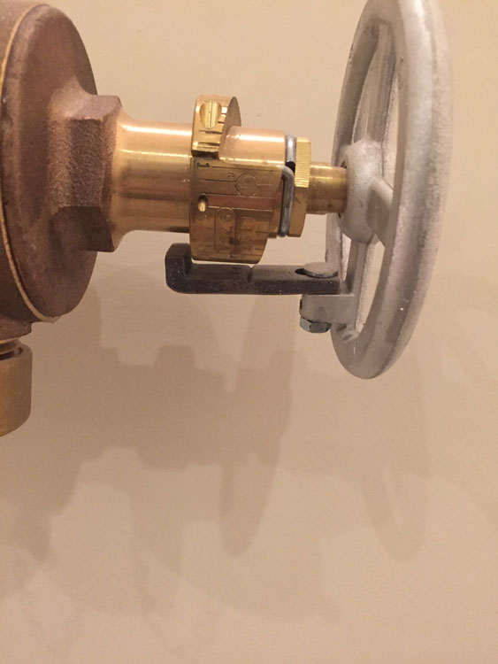
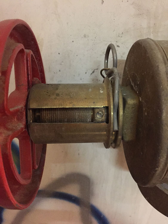
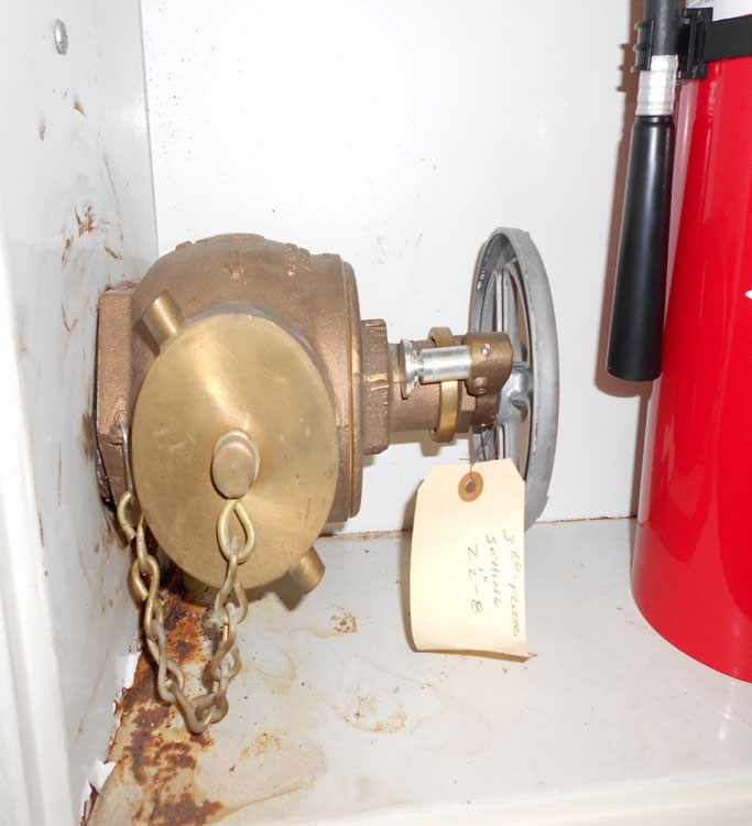
Recall that we briefly mentioned pressure regulating devices. PRDs reduce pressure and flow by interfering with or restricting the size of the orifice. They may be metal rings placed inside of the standpipe outlet to create a smaller orifice or they may be a stopper added to the standpipe wheel to keep it from opening past a certain point. There are multiple different types. Research and become familiar with them all (photos 3-5). When encountered they should be removed prior to connecting fire department hoses or appliances. Some can be removed by having the proper hex key or being broken off with a striking tool.
(6)
(7)
(8) Anthony Rowett Jr, Mobile Fire
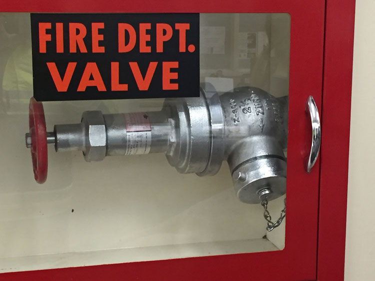
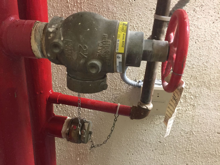
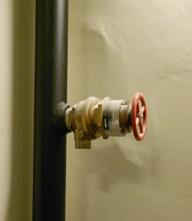
The other common devices to reduce pressure are PRVs These valves maintain a constant flow pressure and gpm despite the system pressure. These valves can be either factory-adjusted (preset) or field-adjustable*. The units that are factory adjusted are specific for each floor and great care must be taken during installation to ensure that they are on the proper floor. The field-adjustable units are field calibrated once they are installed on the floor by a technician. Another small subset of field-adjustable are what some people refer to as fireground adjustable. These can be adjusted by fire department personnel with the right know-how, and they require specific rods to manipulate. PRVs are usually distinguishable by a large rim on the top or bonnet of the valve (photos 6-8), but this is not always the case (see Zurn/Wilkins and Croker systems). Also, once the end cap has been removed, the presence of a smooth stem is a direct sign of a PRV (photo 9). A non-PRV would have a threaded stem (photo 10.). PRVs can also be installed at ceiling level, reducing pressure before water flows to the hose outlet or sprinkler system. This is common in combination systems where the sprinkler system and standpipe system share a common riser. Sprinklers require higher pressures than standpipes due to friction loss in smaller piping and higher operating pressures. In this situation, the system can share one PRV, reducing pressure before separating into the sprinkler piping and standpipe system for the floor. In addition, PRVs are a one-way valve relying on pressure from behind to open the valve. When it comes to pumping buildings there are two main concerns. First is that each valve has required system pressure, which will cause the valve to unseat. If you take over the system, pump the system demand pressure to get the rated outlet pressure for the valve. Second, during FDC emergencies, often the driver’s first thought is to pump into the standpipe itself via the first-floor outlet. The PRV is a one-way valve that is opened by pressure on the back side. You will not be able to pump into a standpipe outlet that has a PRV; it will close the valve shut. We will discuss pumping these systems in further detail later on.
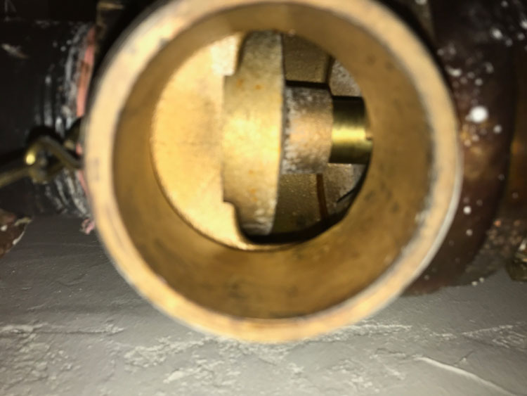
(9) Anthony Rowett Jr, Mobile Fire
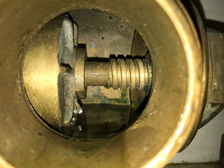
(10) Anthony Rowett Jr, Mobile Fire
Once again, there are plenty of different types of PRVs, and you should research and be familiar with each. If your jurisdiction has fireground adjustable PRVs, ensure the adjusting rods are present during your preincident plans and possibly carry some in your standpipe bag. As mentioned earlier, one of the most famous high-rise fires where PRVs caused severe problems was One Meridian Plaza in Philadelphia. While the PRVs were field adjustable, during installation they had been improperly set, causing firefighters to have standpipe outlet pressures around 45 psi. This case study is an important one in the history of high-rise tactics and equipment and showcases the need for low pressure weapons such as 2 ½-inch hose and smooth bore nozzles. Again, this is what brought about the 1993 edition of NFPA 14 and increased minimum pressures.
Everything is interconnected, and firefighters cannot make decisions without the proper knowledge. Knowledge of these systems is important whether you are working in the building or putting your equipment together.
In part 2 of this series, we will cover nozzle selection, hose selection, and equipment needed for standpipe operations.
END NOTE
* Factory-set valves have no springs, whereas field-adjustable valves are adjusted by tensioning a spring. Factory-set valves have a floating piston/valve assembly that responds to pressure downstream of the valve. The pressure-reducing effect of factory-set PRVs is determined by the surface area of the piston in the piston/valve assembly. Hence, a PRV on a lower floor would have a piston with a larger surface area than one on an upper floor.
 Clay Magee is an instructor with Magic City Truck Academy and a Firefighter/Paramedic with Birmingham (AL) Fire and Rescue and Chelsea Fire and Rescue. He is currently assigned to Rescue 20 at Birmingham. Clay began his career with the East Oktibbeha Fire Department in 2004 while attending Mississippi State University. He has been with Birmingham Fire since 2013. He has a passion for forcible entry and high-rise operations. He holds a bachelor’s degree in business administration from Mississippi State University, an associate’s degree in Fire Science from Columbia Southern University, and multiple certifications from the Alabama Fire College.
The Ins and Out of the Halligan
Part 1: Chief and His Ugly Bar

